



Four-leaf clover triboelectric nanogenerator based on magnetic force separation principle
 0
0 
Abstract
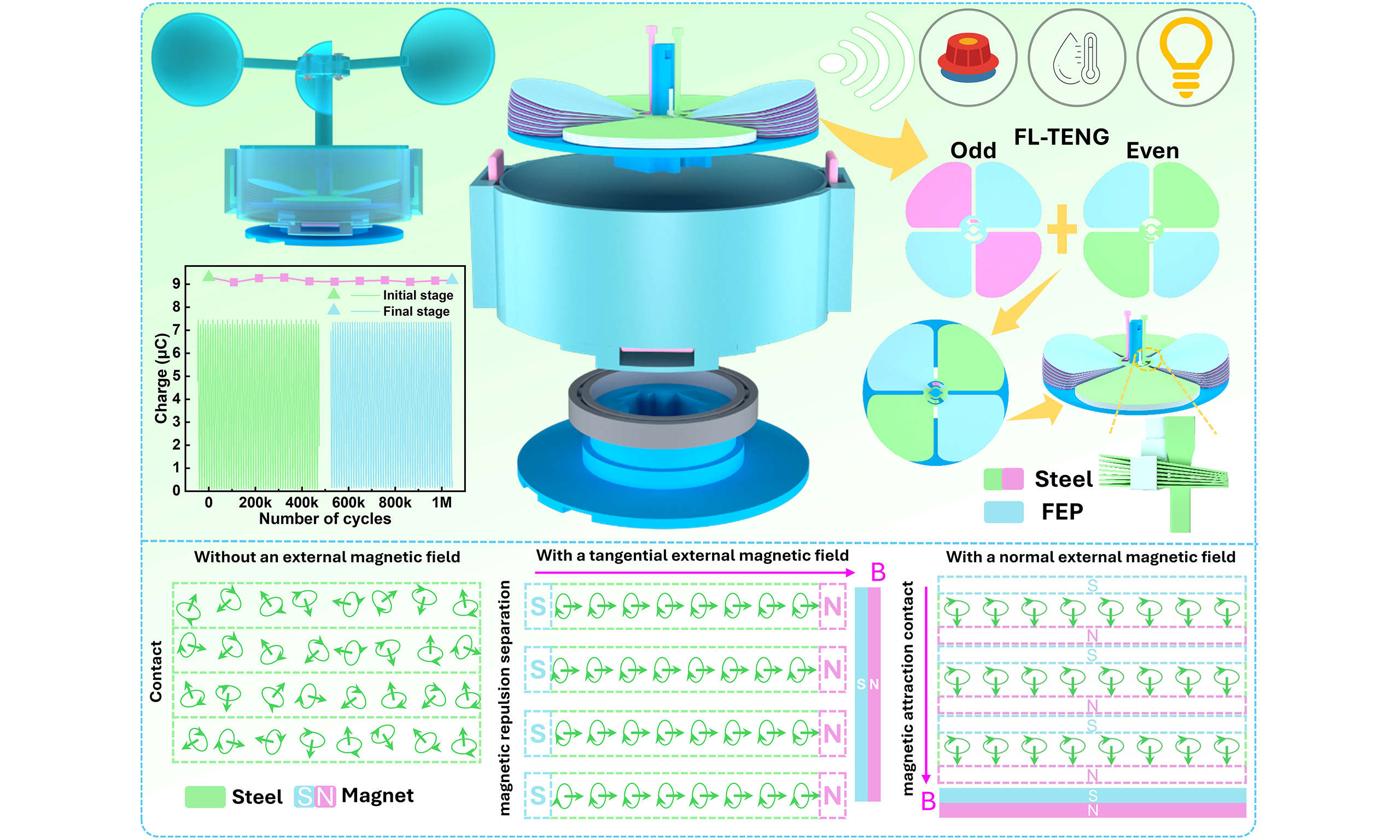
High-density friction layers serve as a key approach for triboelectric nanogenerators (TENGs) to achieve high-performance output and large-scale commercialization. Conventional strategies rely on bulky accessories for uniform force and ordered separation of dense friction layers, which increases device volume and fabrication costs. Here we introduce the magnetic force separation principle relying on the magnetizability of silicon-manganese steel into TENGs for the first time and propose a four-leaf clover TENG (FL-TENG). It leverages the normal and tangential magnetization of steel sheets to generate alternating magnetic attraction and repulsion between steel sheets, enabling ordered contact-separation of the friction layer without complex accessories. In this mechanism, interlayer magnetic repulsion dominates layer separation, while magnetic attraction provides auxiliary contact. FL-TENG is fabricated from laser-engraved four-leaf clover steel sheets, with an alternatingly coated method and thimble design. It eliminates extra accessories to save space and costs and streamline fabrication, and its configuration matches rotating magnetic fields for periodic contact-separation. Furthermore, we investigate the mechanism of magnetic force separation and optimize the output performance of the FL-TENG. Under simulated wind with only two lateral magnets, FL-TENG delivers a peak transferred charge of 13.43 μC and open-circuit voltage of 254 V. After 1,044 k cycles, its output decreases by only 1.29%. The FL-TENG can power miniature electronic devices owing to its favorable output performance. This work provides a robust vertical contact-separation mechanism for high-density stacked TENGs and a new strategy for low-wear wind energy harvesting. With a simplified structure and low-cost raw materials, the FL-TENG boasts potential for application and commercialization.
Keywords
INTRODUCTION
In recent decades, the rapid development of internet of things (IoT) technology has driven the intelligent upgrading of many fields such as environmental monitoring, smart agriculture, and intelligent forestry[1-4]. Intelligent data acquisition in these scenarios is inseparably supported by sensor technology[5]. Sensors usually rely on power supplies such as batteries, but batteries suffer from drawbacks including limited energy storage capacity and environmental pollution risks[6], which can hardly meet the large-scale energy supply demands of the IoT era. Renewable energy is regarded as the optimal approach to address energy demand issues[7], mainly including solar energy[8], thermal energy[9], wind energy[10,11], wave energy[12,13], among others. Among them, wind energy is one of the most promising renewable energies with wide global distribution and abundant reserves, and is also considered one of the most cost-effective power generation methods[14]. However, traditional wind energy harvesting mostly adopts electromagnetic generators based on the principle of electromagnetic induction, which are limited by complex structure, large volume, strict installation conditions, and high construction costs, making them difficult to adapt to the power supply requirements of small electronic devices[15]. As a novel energy harvesting technology, triboelectric nanogenerators (TENGs) possess the advantages of flexible structure, simple fabrication, low cost, wide material selection and light weight, and have become one of the potential core technologies for efficient wind energy harvesting[16]. Over the past decade, numerous researchers have conducted in-depth explorations around structural design, energy management, material innovation, and other aspects, promoting continuous breakthroughs in wind-driven TENGs[17-20]. For instance, to reduce the starting wind speed and realize omnidirectional breeze wind energy harvesting, Archimedean spiral blades integrated with a wind vane were adopted, successfully achieving wind direction adaptability and reducing the starting wind speed[21]. A tightly coupled triboelectric-electromagnetic hybrid generator was proposed with an introduced energy management circuit, significantly enhancing the integration and energy output of hybrid generators[22]. To boost output performance, Wang et al. incorporated barium titanate and carbon nanotubes into a polydimethylsiloxane substrate to fabricate a rotational hybrid triboelectric-electromagnetic wind harvester with a total peak power of 0.18 W, capable of powering agricultural environmental monitoring sensors[23]. Although remarkable breakthroughs have been made in the research of wind-driven TENGs, many challenges still exist, and a long road remains before achieving large-scale industrial application and continuous power supply for IoT sensors.
In general, wind-driven TENGs can be classified into two main categories according to energy harvesting modes. The first type is the flow-induced vibration TENG, which is usually composed of flexible film triboelectric materials (polytetrafluoroethylene [PTFE], fluorinated ethylene propylene [FEP], etc.), conductive electrodes (carbon, aluminum, copper, etc.), and supporting frameworks[24-27]. When airflow passes through the device, the resulting structural deformation gives rise to aerodynamic vibrations, which can be categorized as vortex-induced vibrations[28], flapping motions[29], and galloping oscillations[30]. The vibration drives the contact and separation movement between the friction layer and outputs electrical energy through the coupling of triboelectrification and electrostatic induction[31]. Most flow-induced vibration TENGs adopt the vertical contact-separation working mode[32,33], which can effectively reduce material wear and further improve the durability of TENGs. However, such structures easily cause charge cancellation due to the asynchronous contact-separation movement inside the same friction layer and between friction layers, making it difficult to realize a high-density friction layer structure. Meanwhile, the output performance is further limited by problems such as limited vibration space, poor motion synchronization, and easy dust adsorption. The second type is the rotary TENG, which generally consists of wind cups, a rotor, and a stator. The stator and rotor are mostly composed of radial grating copper electrodes fabricated by printed circuit board (PCB) technology[34-36]. The device captures wind energy through wind cups and converts it into rotational mechanical energy, thereby driving the friction layers to undergo tangential motion. TENGs based on rotational structures usually have a relatively simple structure and can also easily realize dense stacking of multilayer structures to achieve efficient charge transfer, which can significantly improve the output performance of TENGs in a limited space[37]. However, the in-plane relative sliding serves as the main motion mode of such devices, and the resulting frictional heat and material wear greatly reduce the operational stability and durability of TENGs. In particular, a wind energy TENG that combines the ultra-high stability of flow-induced vibration structures and the easy-integration and high-output performance of rotational structures is highly anticipated in this field.
Inspired by industrial magnetic sheet separators, we propose a four-leaf clover triboelectric nanogenerator (FL-TENG) based on the magnetic force separation principle to improve wind energy conversion efficiency via an innovative separation mechanism. As illustrated in Figure 1A, the stator is formed by stacked spring steel sheets with a four-leaf clover outline. Lateral and bottom magnets installed on the rotor alternately exert tangential and normal magnetization on the steel sheets during rotation. The resulting interlayer magnetic repulsion serves as the primary driving force for layer separation, whereas magnetic attraction contributes to auxiliary interfacial contact. Dense steel sheets on each blade thus achieve alternate separation under magnetic repulsion and contact under magnetic attraction for efficient electric energy generation. The alternatingly coated method and thimble connection structure are applied to eliminate charge cancellation. This structural architecture eliminates the extra internal space required by conventional wiring schemes and enables tighter interfacial contact between stacked friction layers. It also removes the need for base frames and counterweights, simplifying fabrication processes and reducing manufacturing costs. In addition, the adopted silicon-manganese (Si-Mn) steel sheets exhibit high magnetic permeability and excellent magnetization stability, and are more cost-effective than common electrode materials including copper and aluminum. The operating mechanism of magnetic force separation, working principle and output performance of FL-TENG are systematically investigated. Maximum transferred charge and open-circuit voltage reach 13.43 μC and 254 V, respectively, in a simulated wind field with only two lateral magnets. The output declines by merely 1.29% after 1,044 k cycles, proving the favorable long-term operating stability of FL-TENG. The FL-TENG can also supply power for electronic devices including calculators, hygrothermographs, and multimeters. This work first proposes a TENG adopting the magnetic force separation principle and applies it to the rotary wind-driven TENG, which delivers an innovative and reliable vertical contact-separation mechanism and provides a new approach for the future large-scale industrialization of TENGs.
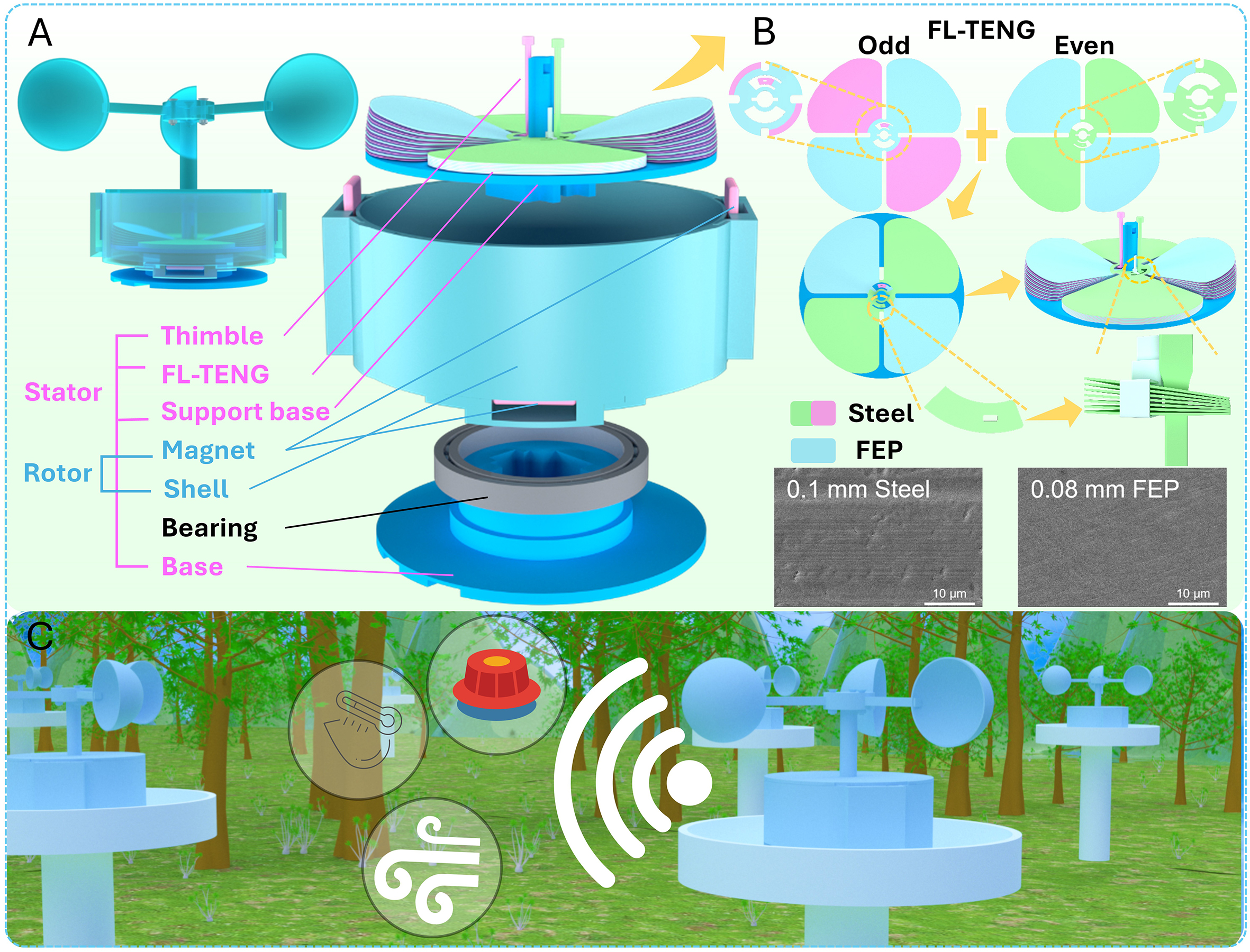
Figure 1. Structure of the FL-TENG based on the magnetic force separation principle. (A) Overall appearance and exploded schematic diagram of the device structure (the shell was designed with four magnet mounting positions: two on the side wall and two at the bottom, allowing flexible configuration for different experimental tests). (B) partial unit structure and material characterization of the FL-TENG. (C) schematic diagram of the application concept of the FL-TENG.
EXPERIMENTAL
Fabrication of the FL-TENG
The main body of the FL-TENG was fabricated using Si-Mn steel sheets (thickness: 0.1 mm, diameter:
Assembly of the entire device
The entire device consisted of a base, a bearing, a shell, NdFeB permanent magnets (grade N52, Dongguan Xinyongquan Hardware and Electronics Company Limited, Guangdong, China; Ganzhou Ruitong Magnetic Materials Company Limited, Jiangxi, China), magnet retainers, the FL-TENG, a support base for the FL-TENG, and wind cups [Supplementary Figures 4-8]. The base, shell, magnet retainers, support base for the FL-TENG, and wind cups were all fabricated using photosensitive resin via 3D printing (Shenzhen Future Workshop Additive Manufacturing Technology Company Limited, Guangdong, China). A three-layer cake-shaped base was placed at the bottom. The inner ring of the stainless-steel bearing (inner: inner diameter
Measurement
The transferred charge, short-circuit current, and open-circuit voltage of the FL-TENG were measured using a Keithley 6514 system electrometer (Keithley Instruments Incorporated, United States of America). The rotational speed of the FL-TENG was regulated by a closed-loop stepper motor (PFDE Automation Company Limited, Zhejiang, China). The wind field was generated by a blower (Model DS-207GF-AC, Wuxi Aotuoman Electromechanical Company Limited, Jiangsu, China), and the wind speed was adjusted by varying the gear or distance of the blower. The wind speed was measured with an anemometer. The magnetic flux density was measured by a handheld digital teslameter (Model TD8620, Changsha Tunkia Measurement and Control Technology Company Limited, Hunan, China). The mechanical force was measured using a universal tensile testing machine (Model TASO TM2101-T7, Dongguan Taishuo Testing Instrument Company Limited, Guangdong, China).
RESULTS AND DISCUSSION
Working mechanism of the magnetic force separation
To address the challenge of separating the friction layer of conventional TENGs caused by air pressure and electrostatic adsorption force, a four-leaf clover triboelectric nanogenerator based on the magnetic force separation principle is designed as shown in Figure 1A and B. This structure innovatively introduces and applies the magnetic force separation principle to rotary TENGs, providing a novel and reliable vertical contact-separation mechanism for TENGs with a dense friction layer and overcoming the traditional in-plane sliding-dominated motion limitation of rotary TENGs. Figure 1C presents the application scenario of FL-TENG in intelligent forest monitoring, and the device can harvest wind energy and convert it into electric power to supply power for small electronic devices such as flame sensors and hygrothermographs.
Figure 1A and Supplementary Figure 4 illustrate the overall structure of the device, which mainly consists of a stator and a rotor. The stator is composed of a three-layer cake-shaped base [Supplementary Figure 5], a support base for the FL-TENG units [Supplementary Figure 6], and the FL-TENG power generation units. The rotor comprises a cylindrical shell [Supplementary Figure 7], magnets (up to four, with two on the side wall and two at the bottom for flexible configuration in different tests), and wind cup. Two magnet retainers are mounted on the side wall of the cylindrical shell at 180° intervals, into which two magnets are inserted from the top. Specific acrylic sheets can be placed between the magnet retainers and the shell to adjust the distance between the magnets and the FL-TENG. Two mounting regions for magnet retainers are also reserved at the bottom of the shell, where two magnet retainers can be installed at 180° intervals (offset by 90° from those on the side wall). To ensure the stability of the entire device during operation, we use a large bearing featuring low friction, high hardness, and excellent durability [Supplementary Figure 8] to assemble the stator and rotor, reducing frictional resistance and improving long-term operational reliability. When the device is placed in a wind field, wind force drives the entire rotor assembly to rotate. At this point, the magnets fixed to the shell move in a circular path and exert an external magnetic field when approaching the steel-sheet-based TENG units. Unlike the conventionally reported magnet-assisted TENGs, such devices realize the contact-separation motion of the friction layer via magnetic interaction between magnets[38] or between magnets and the friction layer[4], and no magnetic interaction exists among the friction layers themselves. In contrast, the magnets inside our device function primarily as magnetization sources to magnetize the Si-Mn steel sheet, thereby inducing magnetic interaction forces between the friction layer (A comparative summary between FL-TENG and other magnet-assisted TENGs is provided in
Specifically, the working mechanism of magnetic force separation consists of two main processes: magnetization and magnetic pole interaction. Magnetization can be interpreted physically from two different perspectives, namely the magnetic charge theory and the molecular current theory, and the analysis in this work is mainly based on the molecular current theory. To clarify the principle in a more accessible manner, the overall model is simplified as shown in Figure 2A. Microscopically, the steel sheets (green rectangles in Figure 2A) contain abundant electrons. The orbital motion and spin motion of these electrons jointly form equivalent annular molecular currents (arrowed rings in Figure 2A). Each molecular current correspondingly generates a tiny molecular magnetic moment (long arrow perpendicular to the ring plane in Figure 2A), whose direction follows the right-hand screw rule with respect to the molecular current direction. In the absence of an external magnetic field, the orientations of the numerous molecular magnetic moments inside the steel sheet are random and cancel each other out, resulting in no macroscopic magnetism. Consequently, the friction layers remain in tight contact due to gravity and their original geometry. Si-Mn steel, also called spring steel, is a typical soft magnetic material with excellent magnetization and demagnetization properties. Figure 2B shows the hysteresis loop of the Si-Mn steel sheet used. It can be seen that under a low-intensity external magnetic field, the mass magnetization (magnetic moment per unit mass) rises rapidly with increasing magnetic field intensity, reflecting the excellent magnetizability of the steel sheet. When the external magnetic field drops from high intensity to zero, the mass magnetization declines sharply to nearly zero. It reveals that the steel sheet retains extremely low remanence once magnetized as the external magnetic field weakens or vanishes, which further verifies its excellent demagnetization characteristic. As the magnet moves in a circular path, it applies an external magnetic field to the steel sheets. Due to the easy magnetizability of the steel sheets, the internal molecular magnetic moments of the steel sheets rotate toward the magnetic field direction under the action of magnetic force, and a large number of these moments rapidly align along the magnetic field direction. As shown in Figure 2C, assuming that the north pole of the lateral magnet is closer to the multilayer steel sheets, a rightward external magnetic field (magenta arrow in Figure 2C) is applied to the steel sheets, and a large number of internal molecular magnetic moments also rapidly rotate to the right and finally align equivalent to the south pole, while the opposite edge region from which the magnetic
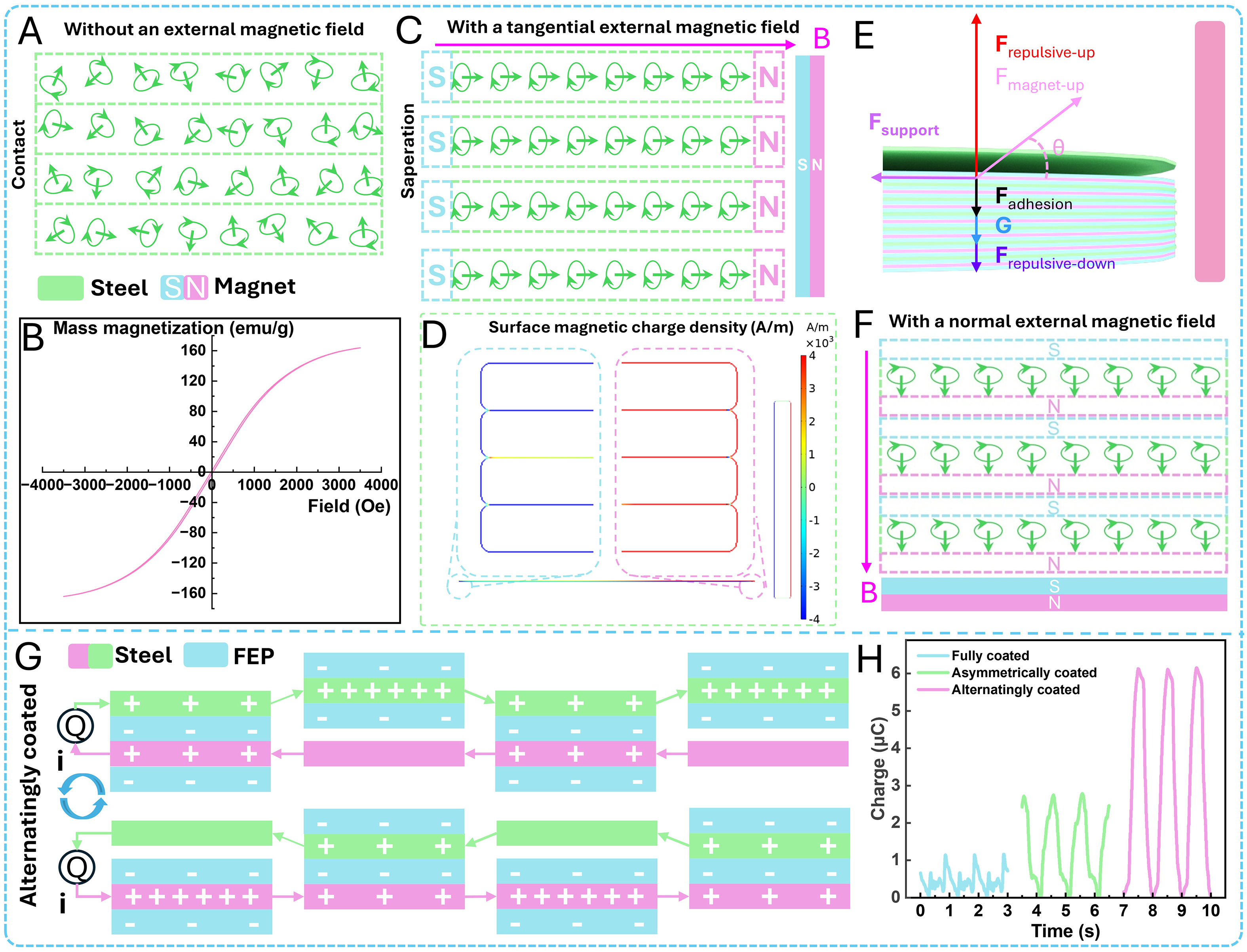
Figure 2. Working mechanism of the magnetic force separation and the FL-TENG. (A) Magnetic moment distribution inside the steel sheet without an external magnetic field. (B) Hysteresis loop of the Si-Mn steel sheet. (C) Magnetic repulsion and separation of the steel sheet due to tangential magnetization under a tangential external magnetic field. (D) COMSOL simulation of the surface magnetic charge density to illustrate the magnetization effect. (E) Force analysis diagram of a single steel sheet in the friction layer. (F) Magnetic attraction and contact of the steel sheet due to normal magnetization under a normal external magnetic field. (G) Working principle of the FL-TENG under the alternatingly coated method. (H) Difference in transferred charge among different coated methods.
moments point away can be equivalent to the north pole. To further illustrate the effect of magnetization, we performed a simulation of surface magnetic charge density without current. As shown in Figure 2D, the end of the steel sheet close to the magnet carries positive surface magnetic charge density, while the end away from the magnet carries negative surface magnetic charge density, which validates our theoretical analysis. Under the magnetizing effect of the external magnetic field, each layer of the multilayer Si-Mn steel sheets can be equivalent to a small magnet, and the same-side edges of each steel sheet are magnetized to the same polarity. Based on the law of like-pole repulsion, magnetic repulsive force is generated between the multilayer steel sheets, which further makes them separate effectively [Figure 2C]. Notably, this magnetic repulsive force has two significant characteristics. First, it is strong at the outer edge regions of the steel sheets, enabling these regions to overcome the inter-sheet electrostatic force and air-locking cavities at the initial separation stage, achieving rapid separation and thereby providing favorable conditions for the subsequent separation of other regions. Second, it maintains high consistency on each steel sheet. Conventional layer-by-layer transmission relying on a medium suffers from problems such as energy attenuation, large differences in separation distance between layers, and medium fatigue. In contrast, the magnetic repulsive force here can uniformly transfer external rotational energy to each steel sheet without medium conduction, achieving effective separation and offering unique advantages.
The aforementioned magnetic repulsive force serves as the core driving force for friction layer separation. To clarify the separation conditions of the friction layer, we analyzed the forces acting on the steel sheets under a static magnetic field. As shown in Figure 2E, excluding the topmost and bottommost sheets, all intermediate steel sheets bear identical types of forces, with each jointly subjected to six types of forces. These include the vertical upward magnetic repulsive force Frepulsive-up from the lower sheet, the oblique upward magnetic attraction Fmagnet-up exerted by the magnet, the interfacial adhesion force Fadhesion that hinders separation (including electrostatic adsorption between sheets, air pressure, and other forces), the self-gravity G of the steel sheet, the vertical downward magnetic repulsive force Frepulsive-down from the upper sheet, and the horizontal limiting force Fsupport provided by the support base. Frepulsive-up and Fmagnet-up act as driving forces that push the steel sheet upward to separate and overcome resistance. Fadhesion, G, and Frepulsive-down constitute downward resistance forces that hinder separation. Fsupport is used to limit the displacement of the steel sheets, preventing the FL-TENG from rotating with the magnet due to the magnetic attraction during magnet rotation, thereby ensuring stable device operation. Based on the force analysis, the condition for steel sheet separation is derived as:
Where θ denotes the angle between Fmagnet-up and the horizontal direction. Because the bottom steel sheet is in direct contact with the support base and has no lower steel sheet beneath it, it is not subjected to Frepulsive-up. In contrast, the top steel sheet has no upper steel sheet above it, and therefore it is not subjected to Frepulsive-down. By comparison, it can be seen that the top steel sheet bears the minimum downward resistance and therefore separates first. As shown in Supplementary Figure 9, as the top steel sheet separates, the vertical downward magnetic repulsive force acting on the next steel sheet gradually weakens. When the resultant force on that sheet satisfies the separation condition, it also separates. Following this rule, the separation propagates downward layer by layer, ultimately leaving the friction layers in a separated state.
It is worth noting that the separation degree differs for the inner and outer regions of the friction layer, with the outer regions exhibiting a larger separation distance [Figure 1A]. This phenomenon is jointly governed by three factors. First, in addition to the six types of forces mentioned earlier, the inner part of the steel sheet bears downward constraints induced by the thimble and cable ties at the central peninsula structure [Supplementary Figure 10], which limit the separation distance of the inner region. The outer part of the steel sheet is far away from the thimble and cable ties, and this constraint force can be ignored, resulting in a larger separation distance in the outer region. Meanwhile, the magnetic field generated by the lateral magnets attenuates from the outer edge to the center. The outer part of the steel sheet possesses higher magnetization intensity, leading to stronger magnetic repulsion between adjacent steel sheets and further widening the separation gap between the inner and outer regions. In addition, the Si-Mn steel sheets are laser-engraved into a four-leaf clover cantilever structure. The central region of the steel sheet features strong bending resistance and hardly undergoes bending deformation. The outer ends of the blades act as free ends and can produce substantial elastic bending driven by magnetic repulsion and other driving forces. This structure effectively increases the outer separation distance and enables coaxial fixation of multilayer steel sheets relying on the central region. Compared with integral circular steel sheets, this four-leaf clover structure perfectly matches the magnetic force separation principle of our device, serving as a key structural innovation of this work.
Based on the clarified static force and separation conditions, we further analyze the dynamic operation process of a single friction layer within the FL-TENG in conjunction with the circular motion of the lateral magnets. With the periodic motion of the lateral magnets, the working states of the friction layer can be divided into four stages [Supplementary Figures 11 and 12]. In stage I, when the magnets are relatively far from the friction layer, the external magnetic field strength within the friction layer area is very weak, and the magnetic repulsive force between the steel sheets is nearly zero. The steel sheets can hardly overcome the downward resistance, and the friction layer remains in a contact state. In stage II, as the lateral magnet gradually approaches the friction layer from the left, the steel sheets in the left region close to the magnet first satisfy the separation condition. Consequently, the left region of the friction layer is in a separated state, the middle region exhibits slight separation, and the right region remains in a contact state. In stage III, when the lateral magnet is directly facing the friction layer, the external magnetic field strength in the middle region reaches its maximum with a more uniform distribution, and the overall separation degree of the friction layer also reaches its maximum. In stage IV, the lateral magnet moves away from the friction layer on the right side. The external magnetic field strength in the left and middle regions gradually decays, while that in the right region gradually increases. Therefore, the left and middle regions of the friction layer gradually return to a contact state, while the separation degree of the right region diminishes. As the lateral magnet continues to rotate, the tangential external magnetic field in each region of the friction layer largely disappears. Because the Si-Mn steel sheets have easy demagnetization properties, the friction layer returns to the same contact state as in stage I. Finite element simulation was performed to analyze the magnetization intensity distribution of the steel sheets during the above four stages [Supplementary Figure 12]. The simulation results correspond to the variation pattern of the external magnetic field strength with the magnet position, verifying that our theoretical analysis of the dynamic working process of the FL-TENG is reliable.
Under the effect of the lateral magnets, the friction layer achieves sufficient separation. As the lateral magnets move away and the bottom magnets gradually approach, the friction layer achieves tighter contact under magnetic attraction, as illustrated in Figure 2F. Assuming that the south pole of the bottom magnet is closer to the friction layer, the friction layer is then exposed to a downward external magnetic field (magenta arrow in Figure 2F), and the molecular magnetic moments inside the steel sheets rapidly deflect downward and align along the magnetic field direction. Similarly, adjacent magnetic moments inside the steel sheets are connected end to end and cancel each other out, leaving only the surface molecular magnetic moments unneutralized, thus exhibiting an overall magnetization effect. We define the surface toward which the magnetic moments point as equivalent to the south pole, and the opposite surface as equivalent to the north pole. At this point, the two contact surfaces of adjacent steel sheets carry opposite polarities. According to the principle of opposite-pole attraction, a magnetic attractive force is generated between each layer of steel sheets, prompting the friction layer to achieve tighter contact.
The above theoretical analysis qualitatively illustrates the operating principle of magnetic force separation. To investigate how the horizontal distance of the magnets from the friction layer affects the layers' separation distance, the magnetic flux density at the outer edges, and the repulsive force between layers, we constructed the test platform shown in Supplementary Figure 13. Two comparative experimental groups (with and without Si-Mn steel sheets) were established. All other variables were kept constant, and the horizontal distance was adjusted incrementally. Throughout the tests, the separation distance of the friction layer, the magnetic flux density at the steel sheet edges, and the tension gauge readings were recorded. The net magnetic flux density induced by the magnetization of the friction layer and the magnitude of interlayer magnetic repulsive force were calculated from the difference in data between the two control groups. As shown in Supplementary Figure 14, the interlayer separation distance, net magnetic flux density, and interlayer magnetic repulsive force all exhibit a decreasing trend as the horizontal distance increases. Finite element simulations were performed to characterize the magnetic flux density for cases with and without steel sheets [Supplementary Figure 14A]. The simulated magnetic flux density agrees well with experimental measurements in overall variation tendency. This phenomenon arises because moving the magnets away from the friction layer reduces the magnetization intensity of the Si-Mn steel sheets, which simultaneously decreases the net magnetic flux density and the interlayer repulsive force, thereby diminishing the separation degree of the friction layers. This set of experiments reveals the variation trends of key parameters governing the magnet-induced separation of the friction layer, providing experimental support for the magnetic force separation principle.
Structure and working principle of FL-TENG
TENGs are one of the potential technologies for efficient wind energy harvesting, yet inferior output performance remains their primary challenge. Adopting a high-density friction layer structure can effectively improve space and material utilization and significantly enhance electrical output. The proposed FL-TENG features such high-density friction layers. Specifically, Figure 1B illustrates the configuration of the FL-TENG (see Supplementary Figure 3 for more details). The TENG unit consists of FEP films, two sets of Si-Mn steel sheets, conductive thimbles, and cable ties, and is mounted on a support base. All Si-Mn steel sheets feature the same pattern (specific dimensions are shown in Supplementary Figure 1) fabricated by laser engraving and present a four-leaf clover structure. For odd-numbered steel sheets (namely negative electrodes), FEP films are attached to any two diagonal blades and the central area excluding the peninsula structure, while the other two blades are left exposed. For even-numbered steel sheets (namely positive electrodes), FEP films are attached to the two diagonal blade positions corresponding to the exposed areas of the odd-numbered sheets, with the remaining parts exposed. It should be noted that to avoid short circuits between the positive and negative electrodes, a film-covered region with a larger radius is reserved at the center of the negative steel sheets, while a bare region with a smaller radius is retained at the center of the positive steel sheets, thereby ensuring insulation at the contact interface between the two electrodes. At the center of each steel sheet, there is a positioning hole composed of a rectangle and a circle, as well as two double-arc fan holes spaced 180° apart. The positioning hole conveniently allows the odd-numbered and even-numbered steel sheets to be alternately assembled onto the protruding rods of the support base, prevents random rotation of the sheets, and ensures stable device operation. The smaller double-arc fan hole contains a peninsula structure, and within this peninsula structure there is a tiny rectangular hole. This hole ensures tight contact between each steel sheet layer and the thimble, thereby ensuring reliable connection of each electrode. The other larger double-arc fan hole prevents short circuits between steel sheets from different groups. This approach of electrical connection via thimbles reduces the space occupation associated with conventional wiring and improves the contact-separation efficiency of the friction layers. The Si-Mn steel sheets used in this study possess good elasticity, flatness, and fatigue resistance, making them excellent materials for constructing high-density stacked TENGs. Figure 1B also shows scanning electron microscope (SEM) images of the Si-Mn steel sheets and FEP films, revealing a certain degree of roughness and a high specific surface area, which are beneficial for storing surface charges and improving the material figure of merit of the TENG. We compared the output performances of FL-TENGs fabricated from FEP, PTFE, and Kapton films under identical conditions, further demonstrating the advantages of the FEP film
The output of FL-TENG is fundamentally derived from the coupling effect of triboelectrification and electrostatic induction. Operating in the vertical contact-separation mode, the device achieves remarkably improved long-term operational stability. When FEP films and Si-Mn steel sheets with distinct electron gain and loss capabilities come into contact, their electron clouds overlap at the microscopic level, and electrons transfer from the higher-energy Si-Mn steel to the lower-energy FEP film. Consequently, bound negative charges accumulate on the FEP film surface, while equivalent positive charges remain on the Si-Mn steel sheet. At the same time, a potential difference is generated between the metal electrodes. Driven by an external magnetic field, the friction layers perform periodic contact and separation motions, altering the potential difference between the electrodes and prompting electrons to shuttle back and forth between the two electrodes to form alternating current. Figure 2G and Supplementary Figure 17 illustrate the working cycles of FL-TENGs fabricated with three different coated methods. Four rectangular units are arranged in each circuit, where rectangles sharing the same horizontal axis form a single group, and these units correspond to the four triboelectric layer sets of the FL-TENG. Since the two magnets mounted on the side wall of the shell are placed 180° apart, during magnet rotation, two diagonal sets of friction layers far from the magnets remain in contact, while the other two diagonal sets close to the magnets remain separated. That is, for the same steel sheet, two blades maintain contact while the other two remain separated. Because the contact-separation states of each set of friction layers in the upper and lower circuits are opposite during operation, their corresponding electron transfer directions are also opposite. To simplify the analysis, only the upper circuit is analyzed below. When the fully coated method is adopted
Output performance
To optimize the output performance of the FL-TENG unit, we established the test platform shown in Supplementary Figure 19 and conducted a series of experiments to analyze the effects of various parameters on output performance. First, the influences of magnet dimensions were investigated. The selected variable dimensions were height (60, 50, 40 mm), width (10, 20, 30 mm), and thickness (3, 5, 10 mm). Considering practical conditions and commercially available magnet specifications, and to reduce the number of experimental groups, we combined the three factors with three respective levels via the orthogonal experimental method, and obtained an orthogonal test table covering 9 groups of magnet dimensions
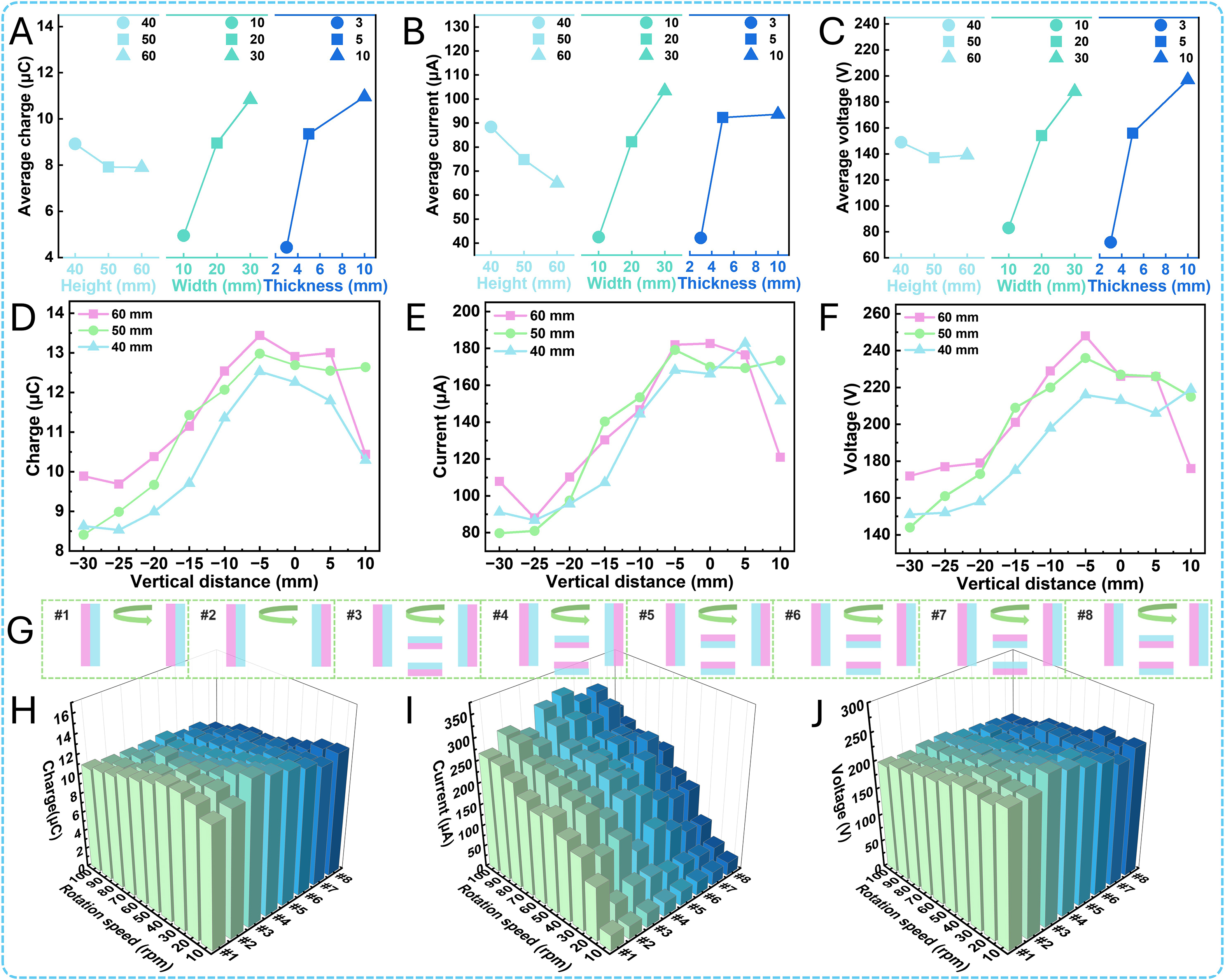
Figure 3. Structural parameter optimization of the FL-TENG. (A) Average transferred charge under different factor levels in the magnet dimension experiments. (B) Short-circuit current. (C) Open-circuit voltage. (D) Transferred charge at different vertical distances between the magnet and the friction layer. (E) Short-circuit current. (F) Open-circuit voltage. (G) Eight polarity arrangements with different magnet quantities. (H) Transferred charge under different rotation speeds and eight magnet polarity arrangements. (I) Short-circuit current. (J) Open-circuit voltage.
Further investigations were conducted on magnet height and the vertical distance between the magnet and the friction layer. The vertical distance h is defined as the perpendicular distance between the bottom planes of the magnet and friction layer, as illustrated in Supplementary Figure 20. The value of vertical distance is positive when the magnet bottom is higher than that of the friction layer, and negative when it is lower. The measurement range spans from -30 mm (the position where the center of the 60 mm-high magnet is aligned horizontally with the bottom of the friction layer) to 10 mm with a step size of 5 mm. Restricted by practical conditions, the magnet width and thickness were fixed at 30 and 5 mm, respectively. For this set of experiments, two lateral magnets were mounted at symmetrical positions with opposite poles directed toward the friction layer, and no magnets were arranged at the shell bottom. The short-circuit charge transfer amount, short-circuit current, and open-circuit voltage of the FL-TENG were measured at a rotational speed of 30 rpm. The results are presented in Figure 3D-F. The optimal performance was obtained at a magnet height of 60 mm and vertical distance of -5 mm, with a charge transfer amount of 13.44 μC, short-circuit current of 181.99 μA, and open-circuit voltage of 248 V. The FL-TENG equipped with a 60 mm-high magnet exhibited superior comprehensive output performance under identical vertical distances. From the overall trend, for a fixed magnet dimension, the output performance first increases and then decreases as the vertical distance rises. The performance peaks within the range from -5 to 10 mm, and most curves reach their maximum values at -5 mm. According to the force analysis of steel sheets in Figure 2E, increasing vertical distance reduces the external magnetic field strength acting on the friction layer, and its magnetization intensity declines, which weakens the magnetic repulsive force between adjacent friction layers. Meanwhile, the vertical component of magnetic attraction force exerted by the magnet on the friction layer increases gradually. Before the output performance reaches its peak value, the enhanced vertical component of magnetic attraction force dominates the variation of friction layer separation degree over the weakened magnetic repulsive force, contributing to improved output performance with growing vertical distance. In contrast, after the peak, the reduced magnetic repulsive force becomes the dominant factor, thus resulting in continuous deterioration of output performance. In addition, under the identical magnet configuration and operating conditions described above, we fixed the vertical distance at 0 mm and characterized the output performance at various horizontal distances between the magnet and friction layer. The results are presented in Supplementary Figure 21. The horizontal distance d refers to the horizontal gap between the outermost boundary of the friction layer and the magnet side facing the friction layer, as defined in Supplementary Figure 22. The test range covers 6 to 22 mm at an interval of 4 mm. It is observed that the output performance declines steadily with the increase in horizontal distance. This is because the growing horizontal distance attenuates the external magnetic field on the friction layer, reduces the separation degree of friction layers, and eventually lowers the output performance.
Since magnets have two polarities (north pole and south pole), different polarity arrangements can affect the magnetization direction inside the steel sheets. Considering that residual magnetism remains in the friction layers after magnetization by the magnets, we also investigated whether such residual magnetism exerts an influence on the subsequent magnetization of the steel sheets. Accordingly, we explored the effects of different magnet polarity arrangements on the output performance of the FL-TENG at various rotational speeds. As shown in Figure 3G, eight distinct magnet polarity arrangements were designed under the same rotational direction. Arrangements #1-2 refer to the lateral magnets facing the friction layers with the opposite polarity and same polarity, respectively. Arrangements #3-5 involve adding two bottom magnets
In addition, several fundamental performances of the FL-TENG were further investigated. First, the output performance of the FL-TENG was explored with different numbers of steel sheets (10, 12, 14, 16, 18, and 20 sheets). The device adopted arrangement #2 (layout #2 in Figure 3G) in this set of tests. Under the conditions of a magnet dimension of 50 × 30 × 5 mm, a vertical magnet distance of 0 mm, a horizontal distance of
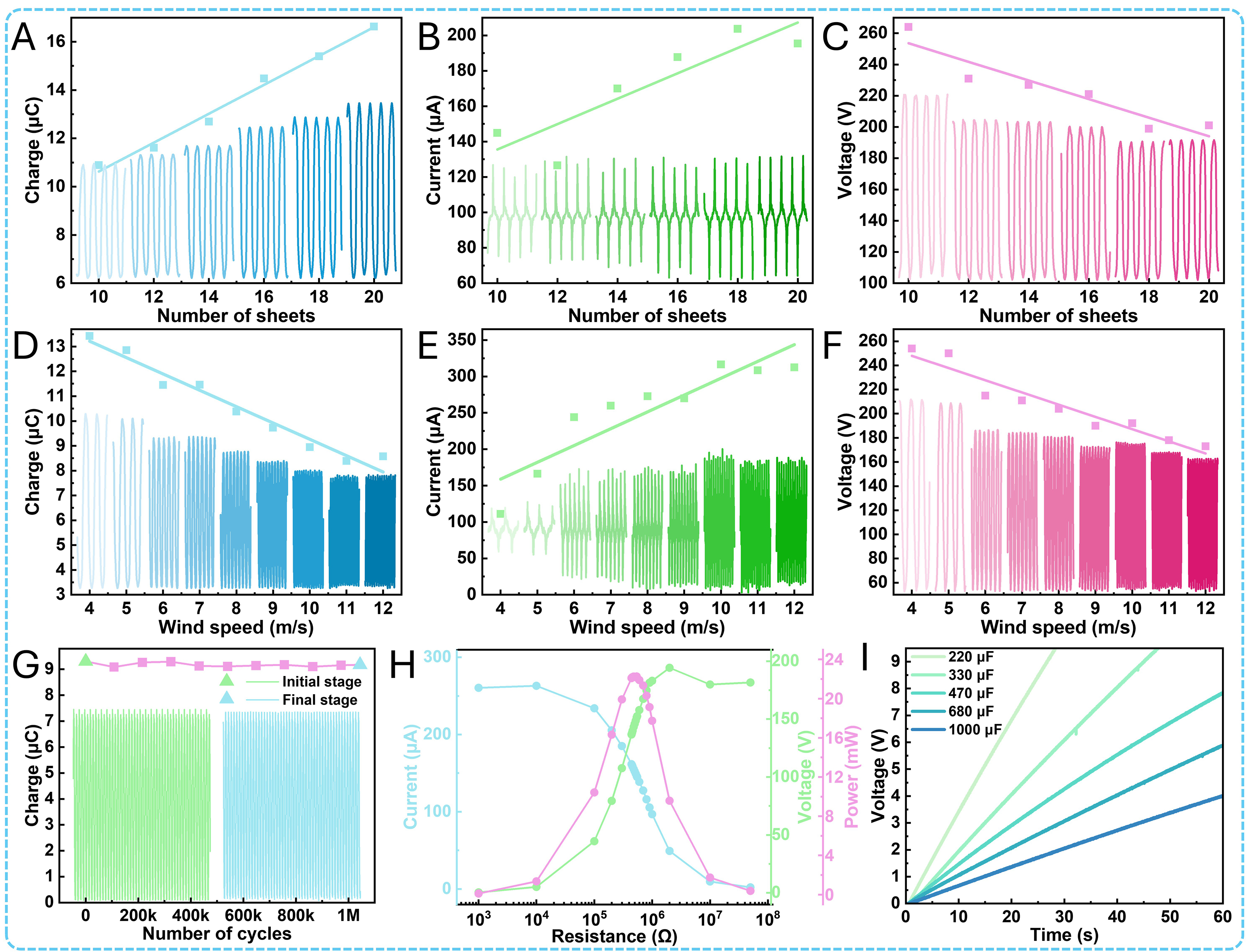
Figure 4. Basic performance of the FL-TENG. (A) Transferred charge at different numbers of steel sheets. (B) Short-circuit current. (C) Open-circuit voltage. (D) Transferred charge at different wind speeds. (E) Short-circuit current. (F) Open-circuit voltage. (G) Transferred charge of the FL-TENG during 1,044 k cycles at 150 rpm, where the green curve represents the initial stage and the blue curve represents the final stage. (H) Output current, voltage, and instantaneous power under different external loads at 100 rpm. (I) Charging voltage curves of different capacitors at 100 rpm.
It can be concluded that the open-circuit voltage decreases with an increasing number of friction layers. Next, the output performance of the FL-TENG under external excitations of different wind speeds was studied. A blower was used to simulate various wind speeds.
The device adopted arrangement #2 (layout #2 in Figure 3G) in this set of tests. Under the conditions of a magnet dimension of 60 × 30 × 5 mm, a vertical magnet distance of -5 mm, and a horizontal distance of
Material wear is the primary cause of output performance degradation. In this work, the magnetic force separation principle was successfully employed to achieve vertical contact-separation of the friction layers, breaking through the conventional in-plane sliding-dominated motion mechanism of rotary TENGs. Adopting arrangement #2 (layout #2 in Figure 3G), the device was operated for more than 100 h under the conditions of a magnet dimension of 60 × 30 × 5 mm, a vertical magnet distance of -5 mm, a horizontal distance of 6 mm, and a rotational speed of 150 rpm. As shown in Figure 4G, after 1,044 k cycles, the transferred charge of the FL-TENG decreases by only 1.29% compared with the initial value of 9.30 μC. The experimental results sufficiently confirm the outstanding long-term working stability of the device.
Application
Investigating the output performance of the FL-TENG under various external load conditions is of great significance for its practical applications. Arrangement #2 (layout #2 in Figure 3G) was utilized for this batch of tests. Herein, the output current and voltage of the FL-TENG under different external loads were measured at a rotational speed of 100 rpm, and the instantaneous power was calculated. The results are presented in Figure 4H. With increasing external load resistance, the current decreases gradually while the voltage increases continuously, and the instantaneous power first rises and then declines, reaching a maximum value of 22.25 mW at a load resistance of 480 kΩ. Therefore, the calculated peak power density and energy conversion efficiency [Supplementary Note 1 and Supplementary Figure 23] are 7.61 W/m3 and 3.13%, respectively. As shown in Supplementary Table 6, the FL-TENG exhibits outstanding wear resistance and output performance compared with other wind-driven TENGs[35,39-43]. To verify the charging capability of the FL-TENG for capacitors, the FL-TENG was connected to a rectifier circuit [Supplementary Figure 24] to charge capacitors with different capacitances (220, 330, 470, 680, and 1,000 μF) under the same conditions mentioned above. The charging curves are displayed in Figure 4I. The voltage of the 220 μF capacitor reaches 9 V after 27 s of charging, and the voltage of the 330 μF capacitor reaches 9 V after 45 s. After 60 s of charging, the voltages of the 470, 680, and 1,000 μF capacitors reach 7.84, 5.87, and 4 V, respectively, confirming that the FL-TENG is capable of charging capacitors.
A wind field was simulated using a blower. Arrangement #2 (layout #2 in Figure 3G) was utilized for all wind field measurements, and the entire device was placed in this simulated field to investigate the wind energy harvesting capability of the FL-TENG based on the magnetic force separation principle. At a wind speed of
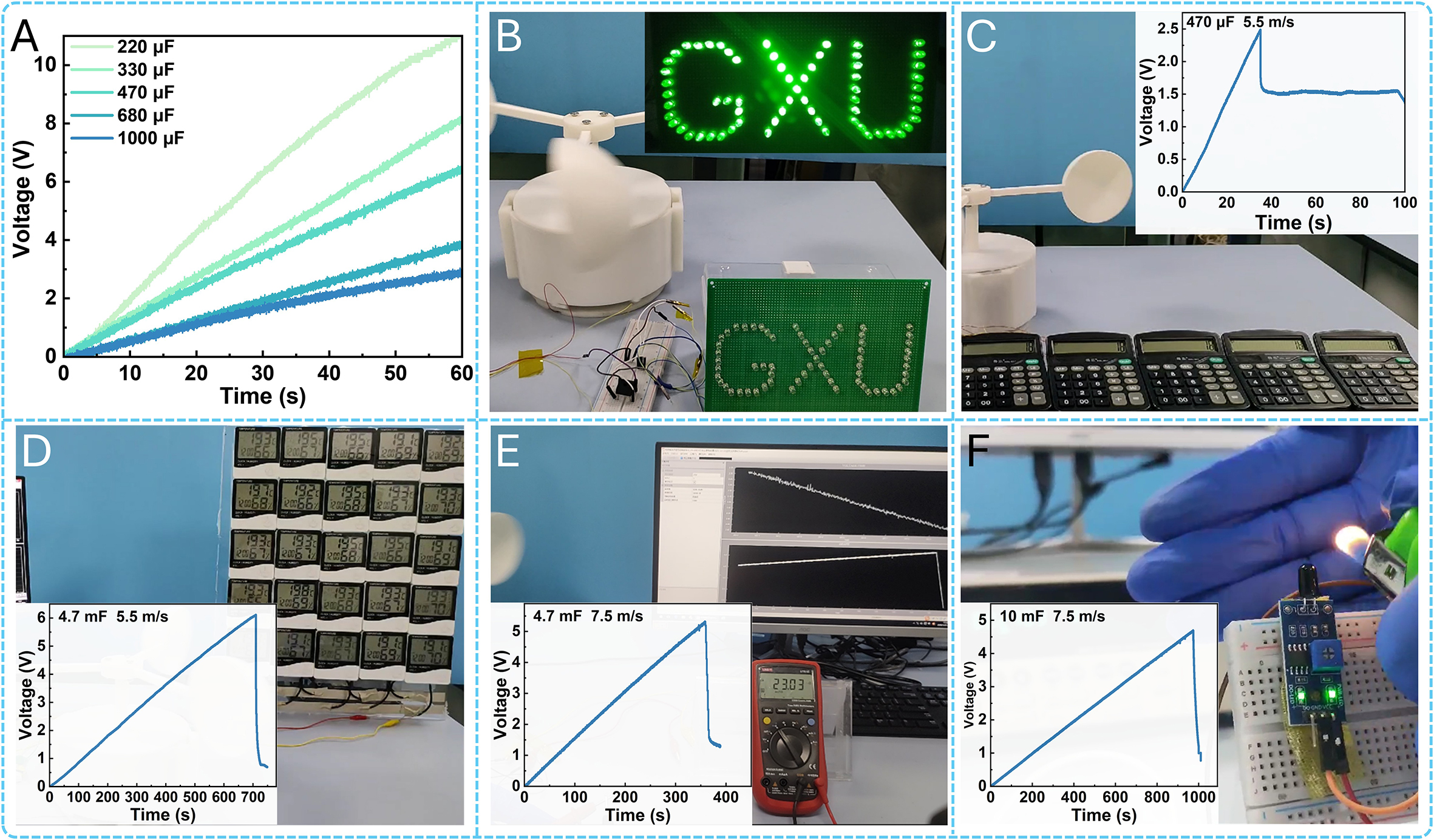
Figure 5. Application demonstration of the FL-TENG. (A) Charging voltage curves of different capacitors at 7 m/s. (B) The FL-TENG lit up the “GXU” logo. (C) Charging a 470 μF capacitor to drive five parallel-connected calculators at a wind speed of 5.5 m/s. (D) Charging a 4.7 mF capacitor to drive twenty-five parallel-connected hygrothermographs at a wind speed of 5.5 m/s. (E) Charging a 4.7 mF capacitor to drive a multimeter at a wind speed of 7.5 m/s. (F) Charging a 10 mF capacitor to drive a flame sensor at a wind speed of 7.5 m/s.
CONCLUSIONS
In summary, we propose a novel driving mechanism based on the magnetic force separation principle and develop a compatible four-leaf clover triboelectric nanogenerator (FL-TENG). By effectively utilizing the normal and tangential magnetization of steel sheets, the dense steel sheets achieve alternate magnetic repulsion separation and magnetic attraction contact, in which magnetic repulsion separation plays a dominant role during device operation, and magnetic attraction contact provides supplementary interfacial bonding, enabling the rotary TENG to operate stably in the vertical contact-separation mode. Featuring an elaborately engraved pattern and a thimble connection, the novel alternatingly coated FL-TENG simplifies the fabrication process, while its four-leaf clover structure can effectively cooperate with a rotating magnetic field to realize periodic contact-separation motion of the TENG. We systematically investigated the working mechanism of the magnetic force separation and the FL-TENG, and explored the effects of magnet dimensions, physical distances between magnets and friction layers, and magnet polarity arrangements on the output performance of the FL-TENG, thereby optimizing the structural parameters. Furthermore, the fundamental performance of the FL-TENG was studied. In a simulated wind field with only two lateral magnets, its maximum transferred charge and open-circuit voltage reached 13.43 μC and 254 V, respectively. After 1,044 k cycles, the transferred charge of the FL-TENG decreased by only 1.29% compared with the initial value of 9.30 μC. In practical applications, the FL-TENG could drive various electronic devices including calculators and hygrothermographs after passing through a rectifier circuit, providing a potentially feasible solution for powering IoT devices. Overall, this study introduces the magnetic force separation principle for the first time, which not only provides a novel and reliable contact-separation mechanism for TENGs, but also offers a new strategy for low-wear and high-stability wind energy harvesting.
DECLARATIONS
Authors’ contributions
Made substantial contributions to conception and design of the study: Feng, S.; Lan, J.; Wu, J.; Tang, W.; Liu, G.; Wang, J.
Performed experimental investigation: Feng, S.; Lan, J.; Wu, J.; Cheng, X.; Duan, J.
Drafted or revised the manuscript: Feng, S.; Liu, G.; Wang, J.
Provided supervision, project administration: Wan, L.; Liu, G.; Li, G.
Availability of data and materials
The data supporting the findings of this study are available within this Article and its Supplementary Materials. Further data are available from the corresponding authors upon request.
AI and AI-assisted tools statement
Not applicable.
Financial support and sponsorship
This work was supported by the National Natural Science Foundation of China (62304058 and 52362025), the National Key R&D Project from the Ministry of Science and Technology (2021YFA1201603), the Innovation Project of Guangxi Graduate Education (YCBZ2023038), the Beijing Key Laboratory of High-Entropy Energy Materials and Devices, Beijing Institute of Nanoenergy and Nanosystems (No. GS2025MS011), the Bagui Young Top-notch Talents Program, and the National Innovation and Entrepreneurship Training Program for College Students of Guangxi University (202510593060).
Conflicts of interest
All authors declared that there are no conflicts of interest.
Ethical approval and consent to participate
Not applicable.
Consent for publication
Not applicable.
Copyright
© The Author(s) 2026.
Supplementary Materials
REFERENCES
1. Sreejith, S.; Panigrahy, A. K.; Ajayan, J.; et al. IoT sensor-based systems in real-time monitoring of health and environment: a review. J. Korean. Phys. Soc. 2025, 87, 1-27.
2. Roostaei, J.; Wager, Y. Z.; Shi, W.; Dittrich, T.; Miller, C.; Gopalakrishnan, K. IoT-based edge computing (IoTEC) for improved environmental monitoring. Sustain. Comput. Inform. Syst. 2023, 38, 100870.
3. Hu, Y.; Tang, R.; Zeng, F.; et al. Self-layered triboelectric nanogenerator for ultrahigh electricity supply. Adv. Mater. 2025, 38, e14186.
4. Zheng, C.; Liang, C.; Wen, H.; et al. Magnetotropic hybrid generator with self-switching mechanism for long-term forest fire prevention. Adv. Mater. Technol. 2024, 9, 2400340.
5. Zhang, F.; Li, D.; Li, G.; Xu, S. New horizons in smart plant sensors: key technologies, applications, and prospects. Front. Plant. Sci. 2025, 15, 1490801.
6. Cai, J.; Wang, H.; Liu, Z.; Zhang, X. Structural design and optimization techniques for the rotational triboelectric nanogenerators - an overview. Renew. Sustain. Energy. Rev. 2026, 232, 116784.
7. Trinh, V.; Chung, C. Use of triboelectric nanogenerators in advanced hybrid renewable energy systems for high efficiency in sustainable energy production: a review. Processes 2024, 12, 1964.
8. Wu, Y.; Qu, J.; Chu, P. K.; Shin, D.; Luo, Y.; Feng, S. Hybrid photovoltaic-triboelectric nanogenerators for simultaneously harvesting solar and mechanical energies. Nano. Energy. 2021, 89, 106376.
9. Zeng, Q.; Luo, Y.; Zhang, X.; et al. A bistable triboelectric nanogenerator for low-grade thermal energy harvesting and solar thermal energy conversion. Small 2023, 19, 2301952.
10. Yu, G.; Ji, P.; Gao, X.; et al. Efficient pedestrian-level wind energy harvesting using a hybridized technology. Energy. Environ. Sci. 2025, 18, 8280-91.
11. Huang, J.; Shao, J.; Zhong, W.; et al. A wind bell inspired triboelectric nanogenerator for extremely low‑speed and omnidirectional wind energy harvesting. Small. Methods. 2024, 8, 2400078.
12. Zhao, C.; Zhang, Y.; Cui, L.; et al. Multifunctional origami-structured triboelectric nanogenerators based on zinc coordination polymers for self-powered photoinduced oxidation systems toward green energy harvesting. Energy. Mater. 2026, 6, 600023.
13. Tang, W.; Li, H.; Li, J.; et al. Rattle drum-inspired triboelectric nanogenerator with enhanced output using charge dispatch and magnetic repulsion pendulum. Nat. Commun. 2025, 16, 9539.
14. Li, J.; Chen, J.; Guo, H. Triboelectric nanogenerators for harvesting wind energy: recent advances and future perspectives. Energies 2021, 14, 6949.
15. Liu, D.; Luo, J.; Huang, L.; et al. Triboelectric nanogenerators as a practical approach for wind energy harvesting: mechanisms, designs, and applications. Nano. Energy. 2025, 136, 110767.
16. Zhou, Y.; Lu, P.; Zhou, X.; et al. Triboelectric wind sensors: fundamentals, progress, and perspectives. Nano. Energy. 2024, 131, 110209.
17. Ren, Z.; Wu, L.; Pang, Y.; Zhang, W.; Yang, R. Strategies for effectively harvesting wind energy based on triboelectric nanogenerators. Nano. Energy. 2022, 100, 107522.
18. Li, Y.; Deng, H.; Wu, H.; et al. Rotary wind-driven triboelectric nanogenerator for self-powered airflow temperature monitoring of industrial equipment. Adv. Sci. 2024, 11, 2307382.
19. Zhang, S.; Shi, Z.; Da, Y.; et al. Harvesting multidirectional wind energy based on flow-induced vibration triboelectric nanogenerator with directional tuning mechanism. Sens. Actuator. A. Phys. 2024, 379, 115974.
20. Hu, X.; Feng, J.; Liang, C.; et al. Round-trip oscillation triboelectric nanogenerator with high output response and low wear to harvest random wind energy. Nano. Res. 2023, 16, 11259-68.
21. Xiong, T.; Xu, Z.; He, Q.; et al. Direction-adaptive triboelectric-electromagnetic hybrid nanogenerator for harvesting omnidirectional breeze wind energy. Nano. Energy. 2025, 143, 111323.
22. Zhou, H.; Cao, Z.; Wang, Z. L.; Wu, Z. A tightly coupled electromagnetic-triboelectric hybrid generator for wind energy harvesting and environmental monitoring. Nano. Today. 2025, 61, 102628.
23. Wang, W.; Yu, S.; Li, P.; Li, Q. Hybrid electromagnetic-triboelectric nanogenerator based on BaTiO3-CNT-PDMS composite for wind energy harvesting. Adv. Mater. Technol. 2026, 11, e02077.
24. Zhang, X.; Wu, H.; Chen, X.; et al. Self-adaptive omnidirectional wind domain energy harvesting based on dual-mode complementary strategy of wind-induced vibration. Adv. Mater. 2025, 37, e12044.
25. Qu, J.; Zhong, H.; Bao, N.; et al. A novel triboelectric generator based on wind-induced film vibration for harvesting breeze energy. Nano. Energy. 2025, 140, 111005.
26. Du, X.; Han, Y.; Guo, D.; et al. Hybrid piezo-triboelectric wind energy harvesting mechanism with flag-dragging the cantilever beam vibration. Nano. Energy. 2024, 131, 110274.
27. Han, Y.; Wu, F.; Du, X.; et al. Enhance vortices vibration with Y-type bluff body to decrease arousing wind speed and extend range for flag triboelectric energy harvester. Nano. Energy. 2024, 119, 109063.
28. Zhang, L.; Meng, B.; Tian, Y.; et al. Vortex-induced vibration triboelectric nanogenerator for low speed wind energy harvesting. Nano. Energy. 2022, 95, 107029.
29. Dong, L.; Tang, Q.; Zhao, C.; et al. Flag-type hybrid nanogenerator utilizing flapping wakes for consistent high performance over an ultra-broad wind speed range. Nano. Energy. 2024, 119, 109057.
30. Wang, Y.; Cai, S.; Wang, Y.; et al. Study on dynamics and power generation performance coupling of galloping-based triboelectric nanogenerator for harvesting broadband wind energy. Nano. Energy. 2024, 130, 110126.
31. Shao, J.; Jiang, T.; Wang, Z. Theoretical foundations of triboelectric nanogenerators (TENGs). Sci. China. Technol. Sci. 2020, 63, 1087-109.
32. Ren, Z.; Wang, Z.; Wang, F.; Li, S.; Wang, Z. L. Vibration behavior and excitation mechanism of ultra-stretchable triboelectric nanogenerator for wind energy harvesting. Extreme. Mech. Lett. 2021, 45, 101285.
33. Zeng, Q.; Wu, Y.; Tang, Q.; et al. A high-efficient breeze energy harvester utilizing a full-packaged triboelectric nanogenerator based on flow-induced vibration. Nano. Energy. 2020, 70, 104524.
34. Zhang, C.; Liu, Y.; Zhang, B.; et al. Harvesting wind energy by a triboelectric nanogenerator for an intelligent high-speed train system. ACS. Energy. Lett. 2021, 6, 1490-9.
35. He, L.; Zhang, C.; Zhang, B.; et al. A dual-mode triboelectric nanogenerator for wind energy harvesting and self-powered wind speed monitoring. ACS. Nano. 2022, 16, 6244-54.
36. Liu, D.; Li, C.; Chen, P.; Zhao, X.; Tang, W.; Wang, Z. L. Sustainable long-term and wide-area environment monitoring network based on distributed self-powered wireless sensing nodes. Adv. Energy. Mater. 2022, 13, 2202691.
37. Zhou, H.; Wei, X.; Wang, B.; Zhang, E.; Wu, Z.; Wang, Z. L. A multi-layer stacked triboelectric nanogenerator based on a rotation-to-translation mechanism for fluid energy harvesting and environmental protection. Adv. Funct. Mater. 2022, 33, 2210920.
38. Li, Z.; Ee, Z. Y.; Gan, W. C.; et al. A magnet-actuated contact-sliding-separation mode triboelectric nanogenerator. Smart. Mater. Struct. 2025, 34, 125029.
39. He, W.; Liu, Y.; Jin, J.; et al. High durability sliding TENG with enhanced output achieved by capturing multiple region charges for harvesting wind energy. Nano. Micro. Lett. 2026, 18, 199.
40. He, Y.; Tang, L.; Zhang, H.; Chen, J.; Yang, X. Rotation-to-translation enabled robust triboelectric nanogenerator for wind harvesting and sensing. Adv. Mater. Technol. 2024, 9, 2302061.
41. Shu, L.; Fang, L.; Wang, F.; et al. Wind speed adaptive triboelectric nanogenerator with low start-up wind speed, enhanced durability and high power density via the synergistic mechanism of magnetic and centrifugal forces for intelligent street lamp system. Nano. Energy. 2025, 133, 110487.
42. Zhu, M.; Zhu, J.; Zhu, J.; et al. Bladeless wind turbine triboelectric nanogenerator for effectively harvesting random gust energy. Adv. Energy. Mater. 2024, 14, 2401543.
Cite This Article
 Open Access
How to Cite
Download Citation
Export Citation File:
Type of Import
Tips on Downloading Citation
Citation Manager File Format
Type of Import
Direct Import: When the Direct Import option is selected (the default state), a dialogue box will give you the option to Save or Open the downloaded citation data. Choosing Open will either launch your citation manager or give you a choice of applications with which to use the metadata. The Save option saves the file locally for later use.
Indirect Import: When the Indirect Import option is selected, the metadata is displayed and may be copied and pasted as needed.
About This Article
Copyright

Data & Comments
Data
0











Comments
Comments must be written in English. Spam, offensive content, impersonation, and private information will not be permitted. If any comment is reported and identified as inappropriate content by OAE staff, the comment will be removed without notice. If you have any queries or need any help, please contact us at [email protected].