



fig3
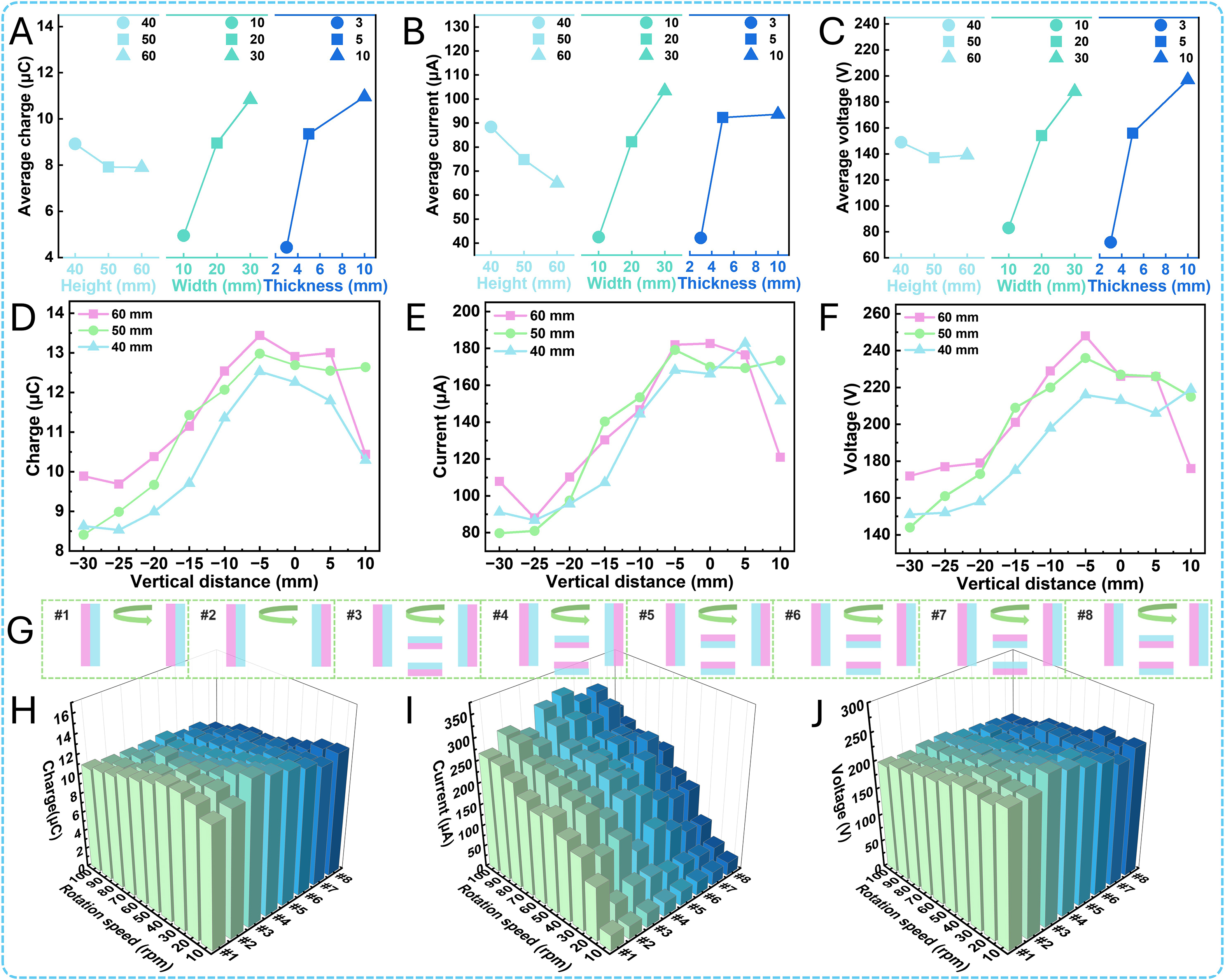
Figure 3. Structural parameter optimization of the FL-TENG. (A) Average transferred charge under different factor levels in the magnet dimension experiments. (B) Short-circuit current. (C) Open-circuit voltage. (D) Transferred charge at different vertical distances between the magnet and the friction layer. (E) Short-circuit current. (F) Open-circuit voltage. (G) Eight polarity arrangements with different magnet quantities. (H) Transferred charge under different rotation speeds and eight magnet polarity arrangements. (I) Short-circuit current. (J) Open-circuit voltage.