



fig4
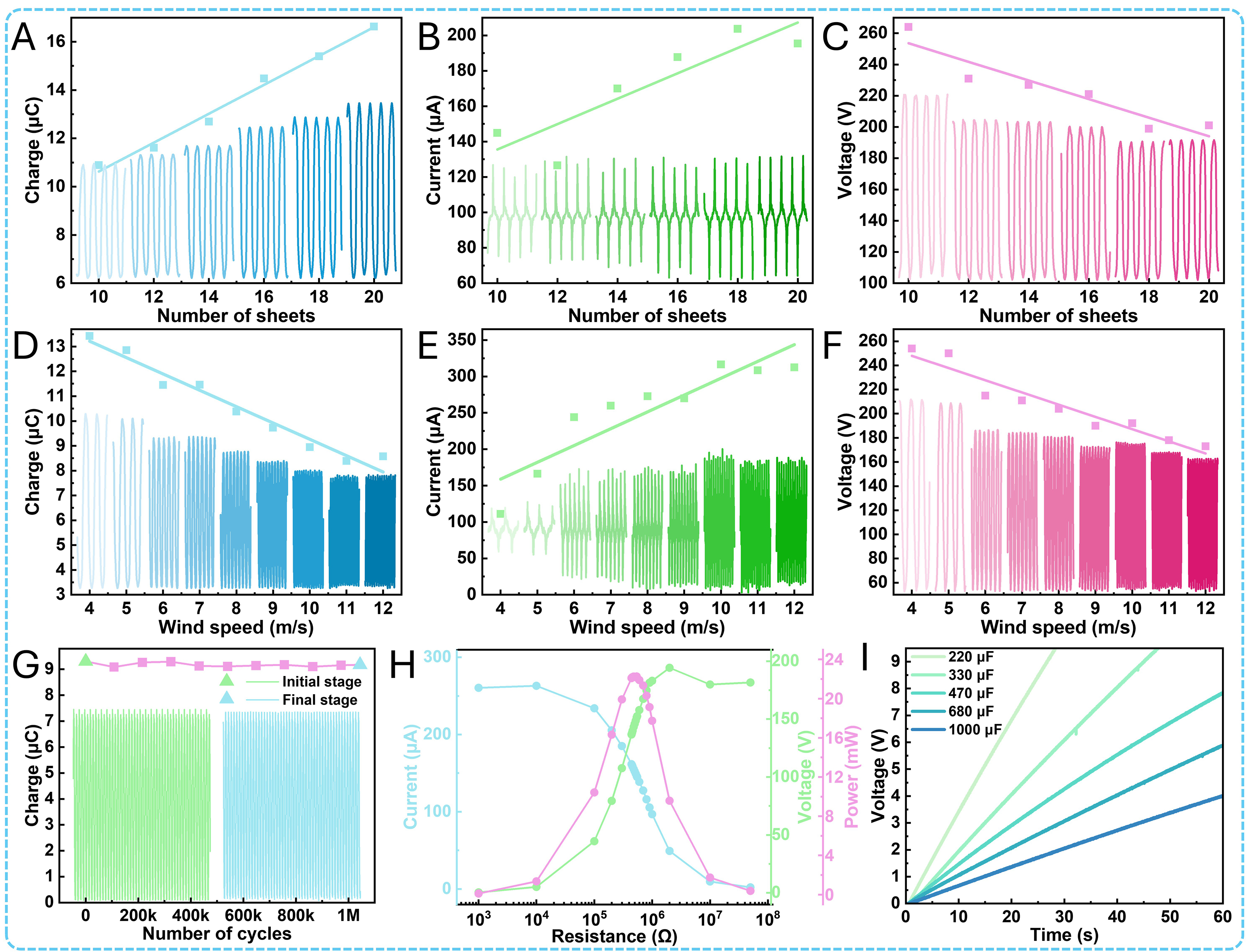
Figure 4. Basic performance of the FL-TENG. (A) Transferred charge at different numbers of steel sheets. (B) Short-circuit current. (C) Open-circuit voltage. (D) Transferred charge at different wind speeds. (E) Short-circuit current. (F) Open-circuit voltage. (G) Transferred charge of the FL-TENG during 1,044 k cycles at 150 rpm, where the green curve represents the initial stage and the blue curve represents the final stage. (H) Output current, voltage, and instantaneous power under different external loads at 100 rpm. (I) Charging voltage curves of different capacitors at 100 rpm.