




fig3
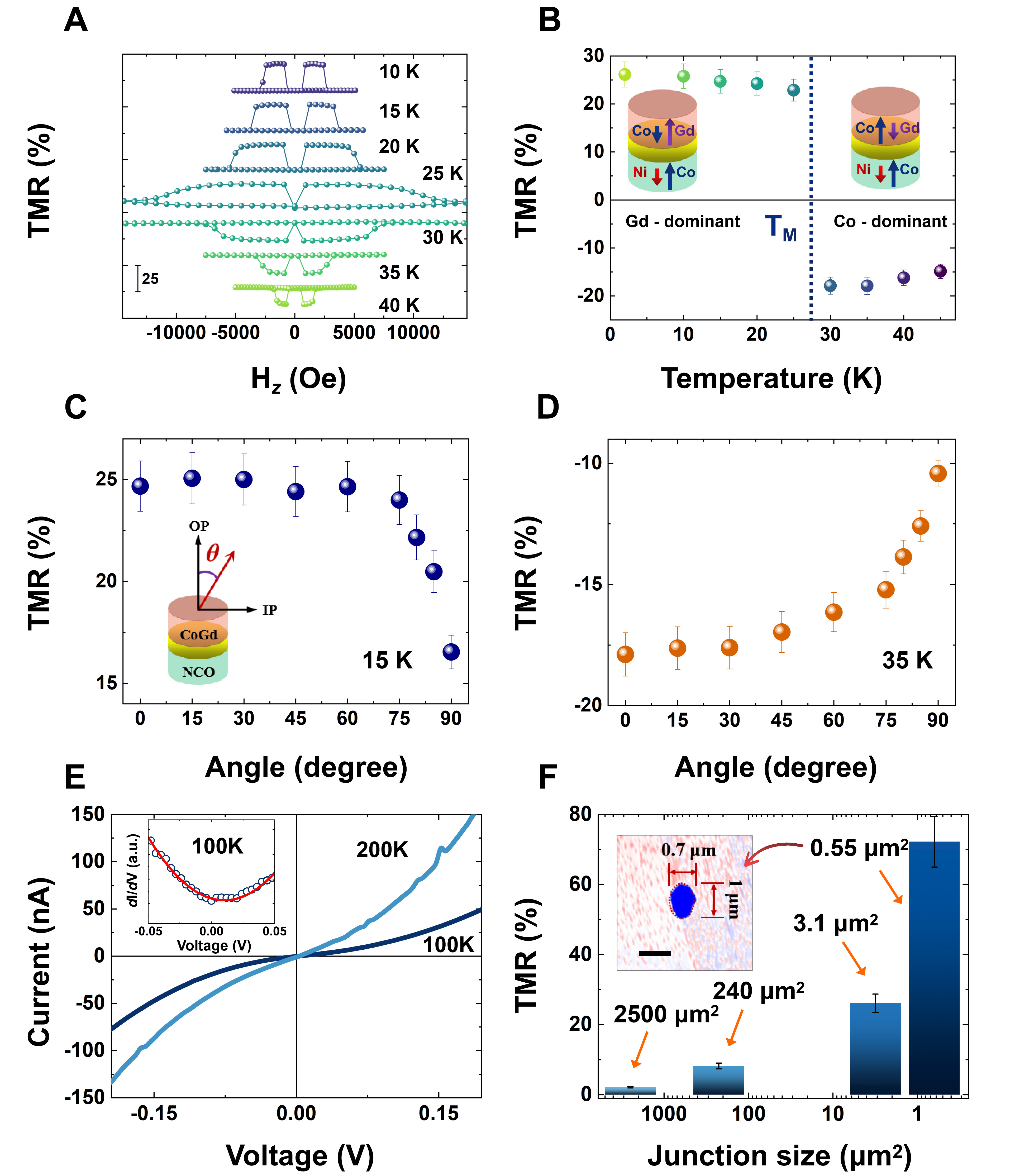
Figure 3. Tunneling characteristics of our perpendicular compensated ferrimagnetic tunnel junctions. (A) TMR loops obtained at various temperatures (using a reading bias of 1 mV); (B) Temperature dependence of the TMR values. Error bars are defined as the standard deviation (SD), the sample size is 3 and the error bars throughout this figure share the same source. Inset: A sketch illustrating the variation of antiferromagnetic coupling in Co82Gd18 when the temperature is below and above TM; The dependence of the TMR value on the angle of the sweeping magnetic field at (C) 15 K and (D) 35 K. In these Figures, 0° and 90° correspond to the out-of-plane and in-plane magnetic field directions, respectively; (E) I-V curves (Dia~56 μm, A ~2,500 μm2) at various temperatures. Inset: Corresponding dI/dV-V curves in the low-bias region at 100 K, fitted using the BDR model; (F) Size-dependent TMR values of our ferrimagnetic tunnel junctions (Circles: Dia 56 μm,





