

fig9
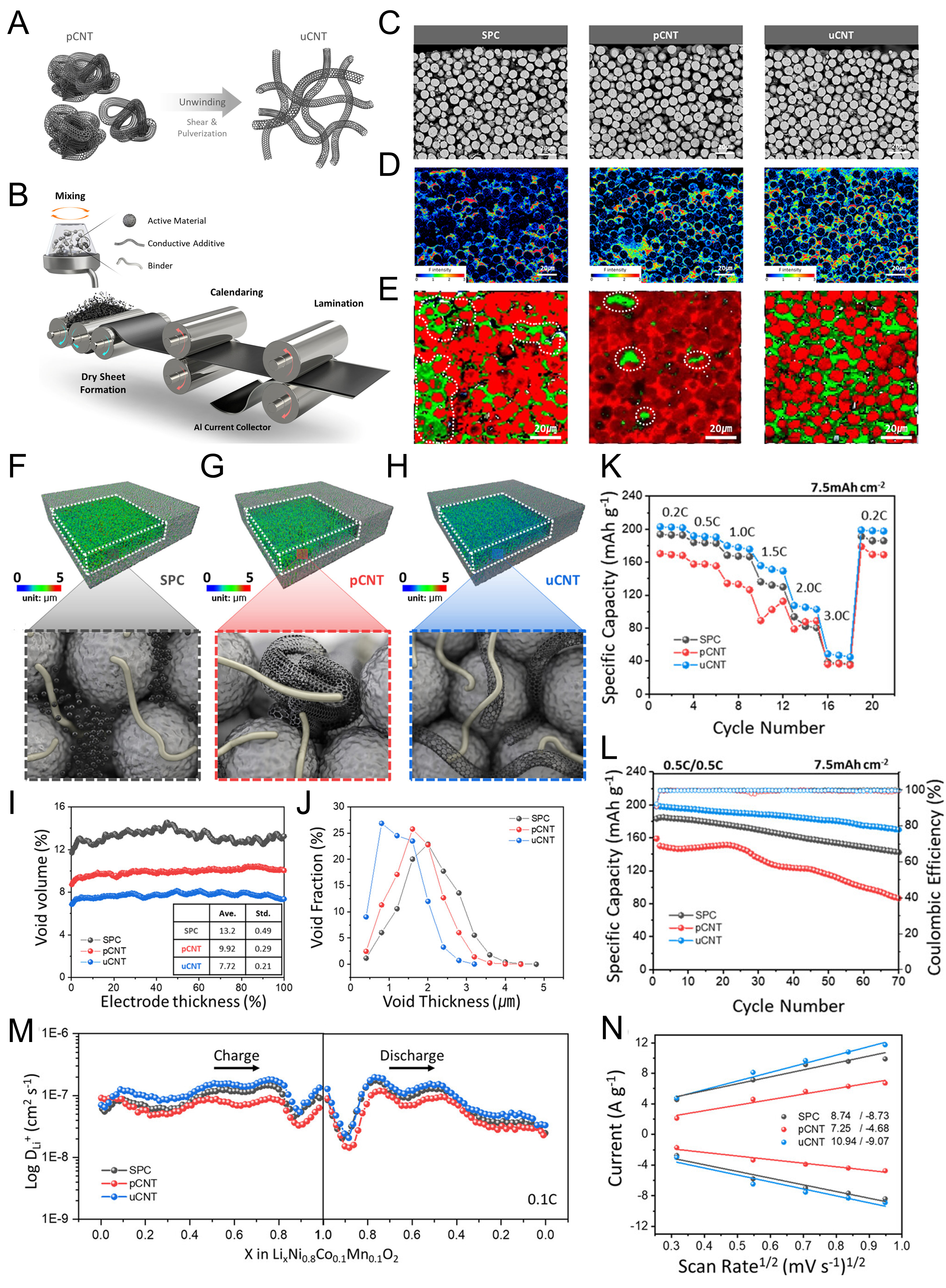
Figure 9. (A and B) Schematic illustration of (A) the unwinding process of entangled CNTs (left) into unwound CNTs (right), and (B) the preparation for fabricating the dry-processed cathode; (C-E) cross-sectional morphology and spatial distribution of binder and conductive networks in dry-processed electrodes; (C) cross-sectional SEM images of SPC, pCNT, and uCNT electrodes; (D) corresponding EPMA WDS elemental maps of F and (E) Raman maps of NCM (red) and carbon (green); (F-H) high-resolution XRM images of (F) SPC, (G) pCNT, and (H) uCNT electrodes; (I) void volume distribution across the electrode thickness obtained from XRM analysis; (J) void-thickness distributions of each electrode obtained from XRM datasets; (K-L) electrochemical performance of half-cells using SPC, pCNT, and uCNT electrodes at 7.5 mAh cm-2; (K) rate and (L) cycling performance; (M) Li+ diffusion coefficients (DLi+); (N) linear relationship between the peak current and the square root of the scan rate; (A-N) are reprinted with permission from Ref.[106] under a CC BY 4.0 license. pCNT: Pristine carbon nanotube; uCNT: unwound carbon nanotube; SPC: Super P carbon; SEM: scanning electron microscopy; EPMA: electron probe microanalysis; WDS: wavelength-dispersive spectroscopy; XRM: X-ray microscopy; NCM: nickel-cobalt-manganese.