

fig8
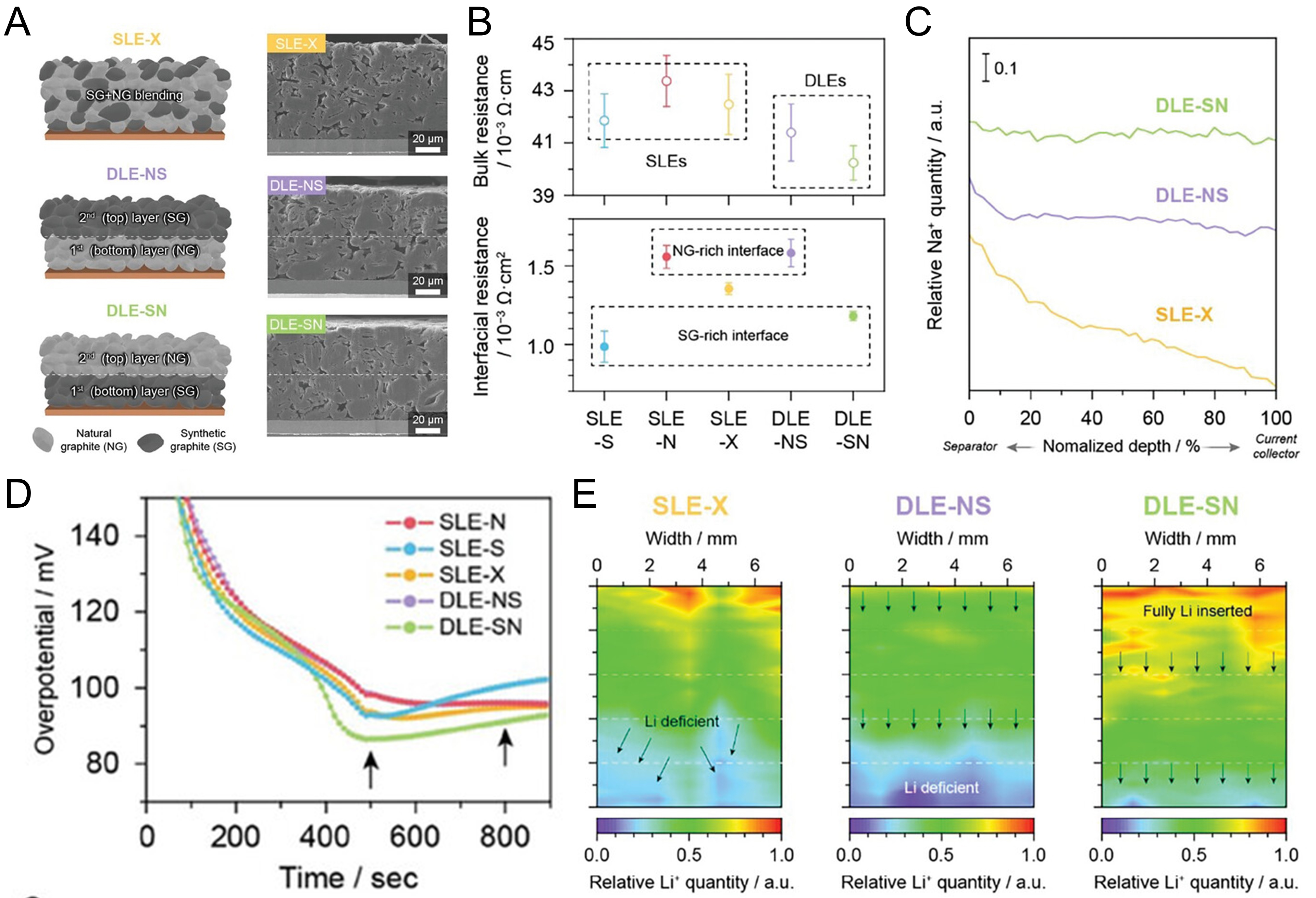
Figure 8. (A) Schematic illustration and FIB-SEM images of as-prepared SLE-X, DLE-NS, and DLE-SN hybrid anodes; (B) selective measurement of interface and bulk resistances of SLEs and DLEs using the electrode resistance measurement system; (C) depth profiles of relative sodium (Na+) counts during Na-LIBS; (D) transient overpotential responses of SLEs and DLEs within 15 min of charging at 4C; (E) Li+-LIBS-guided Li+ distribution maps obtained after the first 4C charge; (A-E) are reprinted with permission from Ref.[88], under CC BY 4.0 license. SLE-X: single-layer electrode containing a 50:50 mixture of natural graphite and synthetic graphite; DLE-NS: dual-layer electrode with natural graphite in the bottom layer and synthetic graphite in the top layer; DLE-SN: dual-layer electrode with synthetic graphite in the bottom layer and natural graphite in the top layer; SLE: single-layer electrode; DLE: dual-layer electrode; FIB: focused ion beam; SEM: scanning electron microscopy.