

fig4
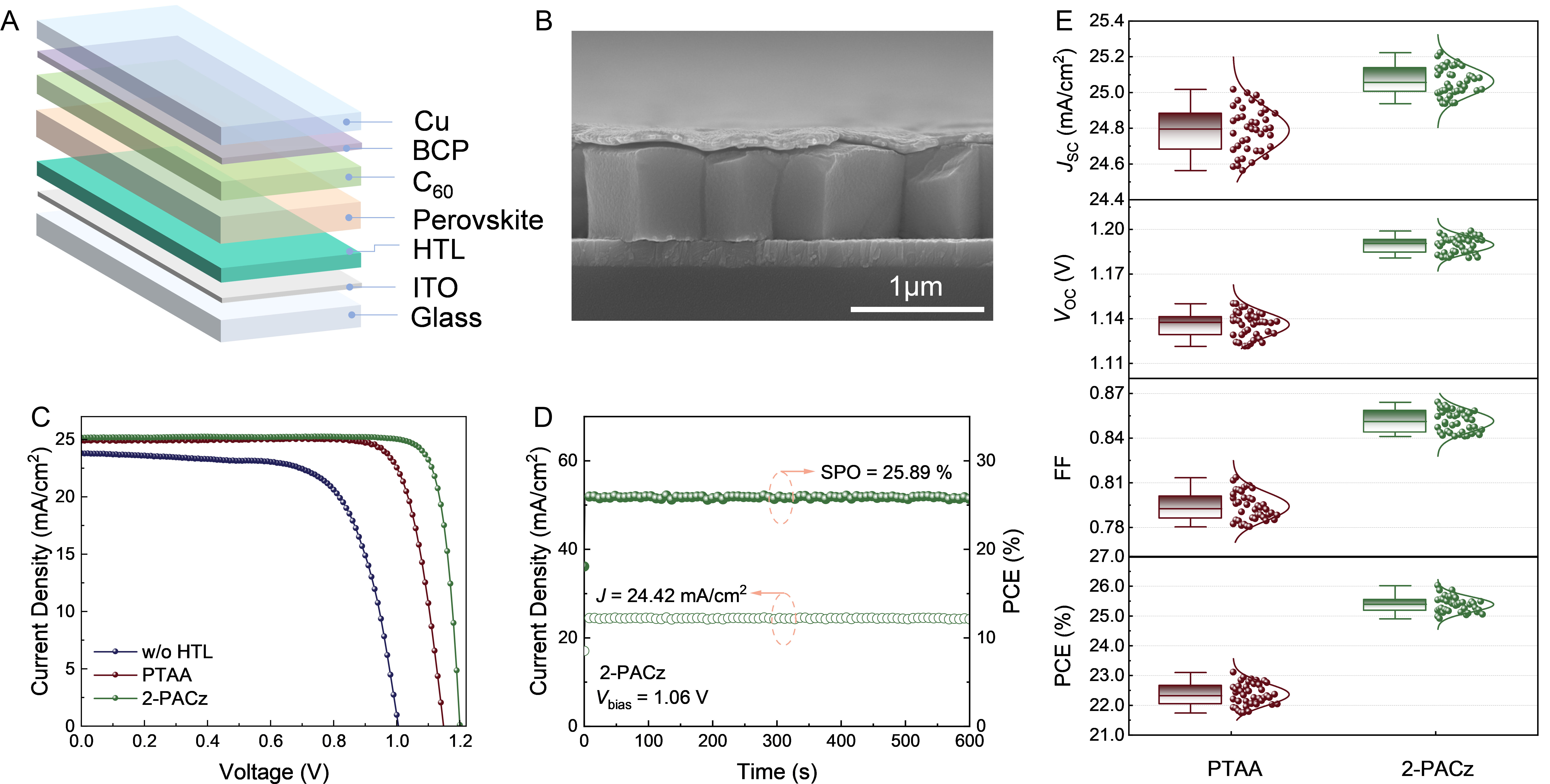
Figure 4. Device configuration and performance. (A) the device architecture of the p-i-n perovskite solar cells; (B) Cross-sectional SEM micrograph of the p-i-n PSCs. The scale bar is 1 μm; (C) J-V curves of devices without HTL, PVK/PTAA, and PVK/2-PACz; (D) The stabilized output of the champion device measured at the maximum power point (MPP) for 600 s. The applied bias voltage is 1.06 V, and the stabilized current density is 24.42 mA/cm2, resulting in a stabilized PCE of 25.89%. A stabilized PCE of 25.89% was recorded for the 2-PACz-based device by tracking its output at the MPP under sustained one-sun illumination; (E) Statistics of the photovoltaic performance parameters (PCE, JSC, VOC, and FF) for PSCs based on 2-PACz versus PTAA HTLs. BCP: 2,9-Dimethyl-4,7-diphenyl-1,10-phenanthroline; HTL: hole transport layer; ITO: indium tin oxide; PTAA: poly[bis(4-phenyl)(2,4,6-triMethylphenyl)aMine]; 2-PACz: [2-(9H-carbazol-9-yl)ethyl]phosphonic acid; SPO: steady-state power output efficiency; PCE: power conversion efficiency; FF: fill factor; VOC: open-circuit voltage; JSC: short-circuit current; J-V: current density-voltage; SEM: scanning electron microscopy; PSC: perovskite solar cell.

