
fig6
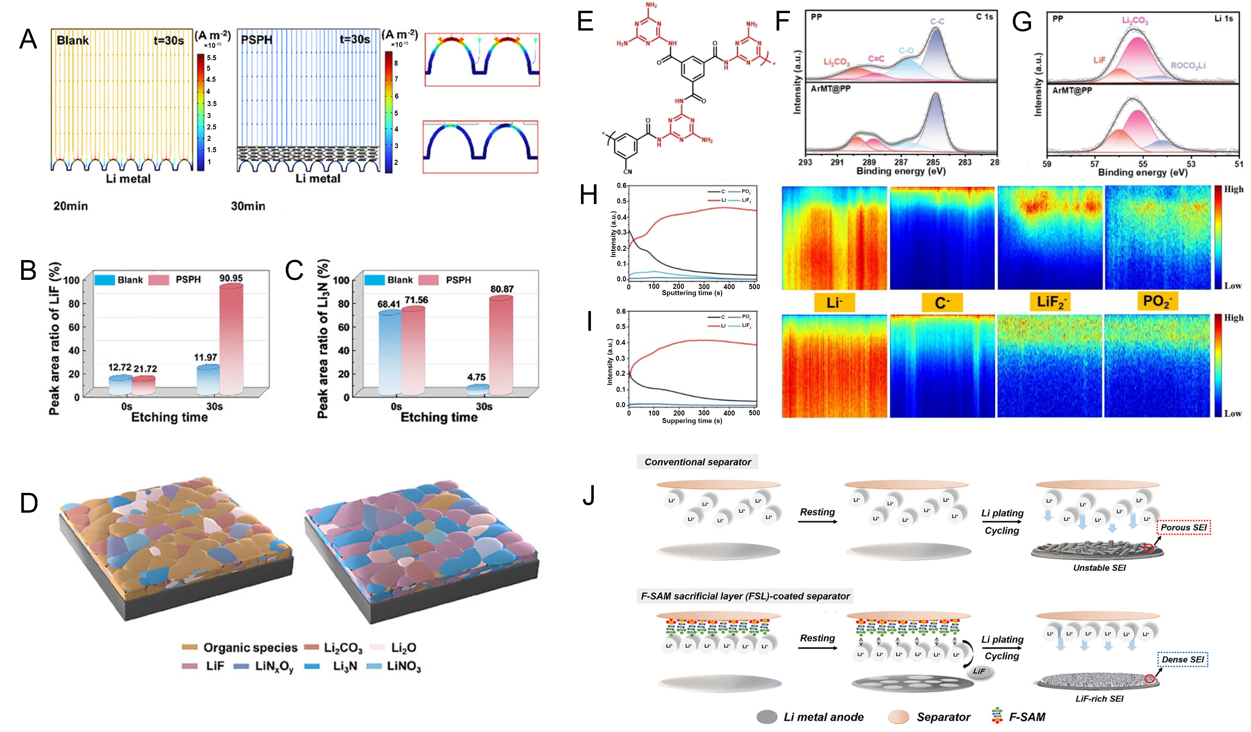
Figure 6. (A) Current density distribution on the lithium metal surface and the corresponding magnified image; (B) Percentage of LiF and Li3N components in the SEI under different separators; (C) Schematic of SEI formation under PP and PSPH@PP separators; (A-C) are reprinted with permission from Ref[223], Copyright © 2025 Wiley; (D) Chemical structure of ArMT; (E and F) C1s and Li1s XPS spectra of lithium metal under PP and ArMT@PP separators after cycling tests; (G and H) TOF-SIMS depth profiling maps showing radial distributions of Li-, C-, LiF2-, and PO2- fragments from lithium metal under corresponding PP and ArMT@PP separators; (I) Schematic illustration of SEI formation mechanisms for conventional separators versus FSL-coated separators; (D-I) are reprinted with permission from Ref[92], Copyright © 2025 Wiley; (J) Schematic image of SEI formation mechanism; (J) are reprinted with permission from Ref[224], Copyright © 2024 Wiley. PSPH: PP: polypropylene; ArMT: a lithium-affinity donor-acceptor polymer; SEI: solid electrolyte interphase; F-SAM: fluorinated self-assembled monolayer; FSL: 3,3,3-trifluoropropylsilane sacrificial layer; XPS: X-ray photoelectron spectroscopy; TOF-SIMS: time-of-flight secondary ion mass spectrometry; ArMT@PP: a lithium-affinity donor-acceptor polymer on PP separator.

