



fig5
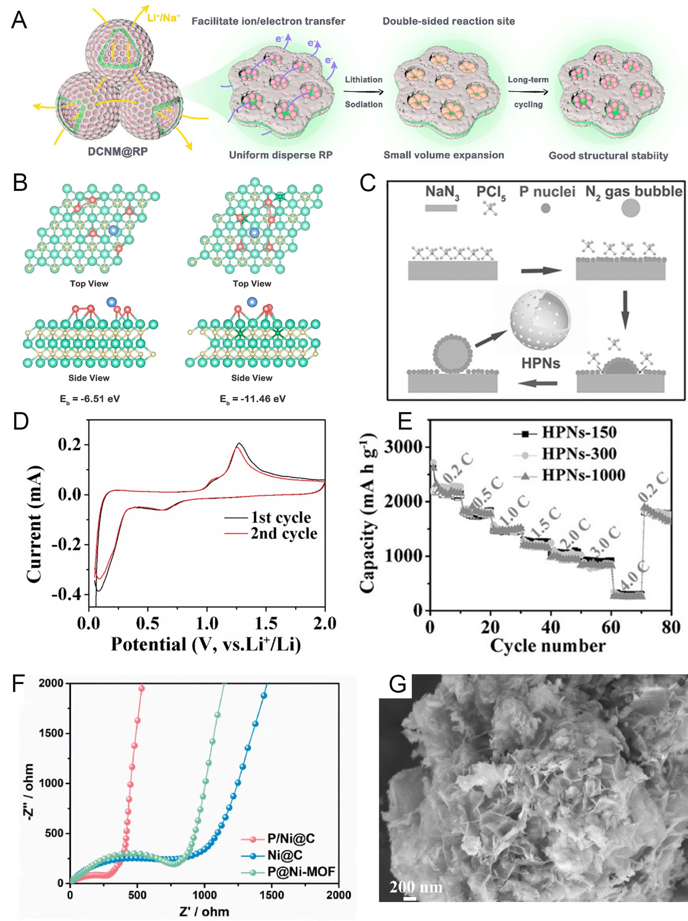
Figure 5. (A) Schematic illustration of the lithiation/sodiation and subsequent delithiation/desodiation processes of RP confined in the pores of DCNM in LIBs and SIBs. (B) Optimized structures and adsorption energies of LiP5 on the Ti3C2 and N-doped Ti3C2 surfaces. Here, blue, red, yellow, light green, and dark green spheres represent lithium, phosphorus, carbon, titanium, and nitrogen atoms, respectively. (C) The schematics illustrate the proposed formation mechanism of the hollow phosphorous nanospheres. (D) The CV curves of HPNs-300 for LIBs anode with a scan rate of 0.1 mV s-1. (E) The rate performance of HPNs with average diameters of 150 (HPN-150), 300 (HPNs-300), and 1,000 nm (HPNs-1000) for LIBs at current densities varying from 0.2 to 10.0 C. (F) Cycling performances of the P@Ni-MOF, P/Ni@C, and Ni@C electrodes. (G) SEM image of P/Ni@C composite. (A and B) are adapted with permission from Ref.[79], copyright 2023, American Chemical Society; (C-E) are adapted with permission from Ref.[80], copyright 2017, Wiley; (F and G) are adapted with permission from Ref.[81], copyright 2022, Elsevier.