


Surface modification and interfacial engineering of Na3SbS4 solid electrolytes by polymethylsiloxane-based polymer for high-performance all-solid-state sodium-ion batteries
 0
0 
Abstract
All-solid-state batteries are regarded as promising next-generation energy-storage systems due to their potential to achieve energy densities exceeding
Keywords
INTRODUCTION
Sodium-ion batteries have attracted considerable attention owing to the natural abundance of sodium resources and high theoretical capacity of sodium metal (1,166 mAh g-1)[1-3], offering strong potential for high-energy-density storage systems. In this context, sodium all-solid-state batteries (Na-ASSBs) have emerged as a promising alternative because of their enhanced safety arising from the use of non-flammable solid electrolytes. However, despite these advantages, achieving stable and long-term cycling remains a significant challenge. Among the various solid electrolyte candidates, sulfide-based materials have received significant attention because of their high ionic conductivity and relatively soft mechanical properties. Representative examples include Na3AsS4 (2.7 × 10⁻⁵ S cm-1)[4], Na3BS3 (1.1 × 10⁻⁵ S cm-1)[5], Na3PS4 (NPS,
On the cathode side, additional instability arises from the intrinsic electrochemical limitations of sulfide electrolytes. Although NSS and NPS exhibit relatively wide electrochemical windows, they undergo decomposition at low potentials (approximately 1.39-2.45 V for NSS and 1.83-1.90 V for NPS)[11,12]. In Na3SbS4, mechanical stress coupled with irreversible chemical reactions leads to the formation of Na-Sb binaries, Na2S, and SbS33- species, which act as mixed ionic/electronic resistive interphases[13-15]. Therefore, stabilizing both anodic and cathodic interfaces is essential for achieving a reliable battery performance.
To address these challenges, artificial interfacial engineering strategies have been extensively explored to regulate the electrode/electrolyte interface[16]. These interlayers serve multiple functions, including suppressing direct interfacial reactions, regulating Na+ flux during stripping/plating, controlling interphase thickness, and reducing interfacial resistance[17]. One common approach involves elemental doping to introduce vacancies or substitutions that facilitate interphase formation, such as NaF- or boride-rich layers through F and B doping[18,19]. However, such doping strategies may adversely affect the mechanical properties of the electrolyte, including Young’s modulus and fracture resistance, thereby limiting their practical applicability[17].
Alternatively, surface and interfacial modification strategies have been developed, including polymer coatings, ionic liquid interlayers[20], alucone coatings[21], and membrane-based approaches[22]. Among these, polymer-based coatings are particularly attractive due to their structural flexibility and strong coordination interactions with Na+ ions. Functional groups such as C=O, -S, and -F in polymer backbones exhibit high affinity for Na+, facilitating ion transport while simultaneously improving interfacial contact[23]. Numerous polymer systems, including poly (vinylene carbonate), polyethylene, PVDF-HFP, polyethylene oxide, and polypropylene glycol, have been reported to enhance ionic pathways and interfacial compatibility in solid-state systems[23,24]. Importantly, the effectiveness of polymer interlayers strongly depends on parameters such as the polymer concentration and operating temperature. A lower polymer concentration can reduce the viscosity, enhance wettability, and improve pore filling, thereby facilitating ion transport[9]. In addition, elevated temperatures significantly enhance Na+ mobility by promoting grain-boundary diffusion within the solid electrolyte and activating segmental motion in polymer chains, enabling efficient ion hopping through coordinated polymer-salt networks[20].
Recent studies on Na3SbS4-based systems have further highlighted the role of polymer interlayers in regulating electrode/electrolyte interfacial behavior. Pristine Na3SbS4 exhibits an ionic conductivity of approximately 3.1 × 10⁻⁴ S cm-1 at room temperature, whereas polymer-modified systems such as PEG-PPG-PEG (PPP)/sodium bis(trifluoromethylsulfonyl)imide (NaTFSI) composites show slightly lower conductivity values of 1.9 × 10⁻⁴ S cm-1 together with increased activation energy (0.20-0.31 eV)[25]. These results indicate that polymer incorporation does not necessarily enhance the intrinsic bulk ionic transport properties of the electrolyte. Instead, the primary effect of the polymer interlayer is associated with interfacial stabilization during electrochemical cycling. For example, bare NSS cells exhibit a substantial increase in electrode/electrolyte interfacial resistance from 318.2 to
Herein, we report the first application of a siloxane-based sodiated polyelectrolyte interfacial layer for Na3SbS4 solid electrolytes. The polymer is based on a poly (dimethyl siloxane) backbone functionalized with ethylene glycol methyl ether, methacrylate, and acrylic acid groups, providing enhanced mechanical flexibility, interfacial adhesion, and Na+ coordination capability[30]. The incorporation of NaTFSI increases Na+ concentration and facilitates ion transport across the solid electrolyte/polymer/electrode interfaces. Furthermore, operation at 55 °C induces a semi-glassy polymer state with reduced viscosity, improving interfacial wetting, filling surface defects, and enhancing electrochemical performance under practical conditions.
EXPERIMENTAL
Preparation of Na3SbS4 solid electrolyte pellet
The Na3SbS4 (NSS) solid electrolyte was synthesized according to our previous report[31]. NSS pellets were prepared from a ball-milled mixture of Na2S (90+% purity, Alfa Aesar, Karlsruhe, Germany), Sb2S3 (98% purity, Alfa Aesar, Germany), and S (99.9% purity, Sigma-Aldrich, Schnelldorf, Germany) in a 3:1:2 ratio. The precursor mixture was ball-milled at 560 rpm for 20 h, followed by thermal treatment at 250 °C for 12 h, as illustrated in Figure 1. The resulting powder was pelletized under a pressure of 360 MPa in an argon atmosphere.
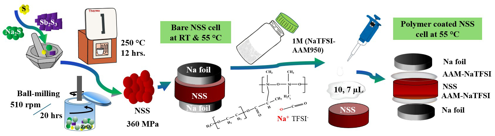
Figure 1. Flow chart of dual side AAM950 polymer coating on the pellet of prepared Na3SbS4 (NSS) solid electrolyte.
Surface modification of NSS pellet-AAM950 polymer coating
The sodiated polyelectrolyte was prepared as described in our previous report[30]. AAM950 polymer, a poly (dimethyl siloxane)-based functionalized polymer, was combined with 1 M bis(trifluoromethylsulphonyl)imide sodium salt (NaTFSI, ≥ 99.5%, Aladdin). NaTFSI was first dissolved in a small amount of dimethyl carbonate (DMC, 99%, Thermos scientific) and ground in an agate mortar for a minute to obtain a concentrated, clear solution. Subsequently, AAM950 polymer was added and mixed until a homogeneous, viscous gel was obtained. A defined volume (5, 7, 10 and, 12 µL) of the gel was deposited onto the surface of the NSS pellet using a pipette and uniformly spread with a spatula, as shown in Figure 1, inside a glove box (H2O < 0.5 ppm, O2 < 0.5 ppm). The DMC solvent evaporated naturally at room temperature within 2-3 min without external heating, leaving behind a uniform polymer coating layer.
Assembly of symmetric sodium all-solid-state cells
Symmetric Na||Na cells were assembled using Na metal foils with an 8 mm diameter (Alfa Aesar) placed on both sides of the 1 M NaTFSI-AAM950/NSS/NaTFSI-AAM950 pellet, as shown in Figure 1. Stainless steel spacers and springs were incorporated into CR2032-type coin cells, and the assembled cells were compressed at 210 MPa to maintain stable interfacial contact.
Fabrication of asymmetric half-cells
Asymmetric half-cells were assembled using Na2/3Fe1/2Mn1/2O2 (NFMO, SKSTC) as the cathode. A slurry comprising NFMO, Poly (vinylidene fluoride) (PVDF) binder, and Super P conductive carbon in an 8:1:1 weight ratio was prepared in N-methyl-2-pyrrolidone (NMP) and stirred overnight to ensure homogeneity. The slurry was cast onto aluminum foil, vacuum-dried at 120 °C for 9 h, and punched into 10 mm diameter electrodes[31]. Sodium metal foil served as the anode, with the AAM950-NaTFSI-coated NSS solid electrolyte positioned between the electrodes in a sandwich configuration. The assembled cells were compacted at
Material characterizations
Raman spectra were obtained using a Raman spectrometer system provided by BWTEK (model BAC102-532E, USA). Fourier transform infrared (FT-IR) spectra were obtained to determine functional groups and bonding through a Bruker Vertex 70 model FT-IR spectrometer (Germany). Morphological and elemental analyses were performed using a field-emission scanning electron microscope (FE-SEM; model JSM-7600F, JEOL, Japan) interfaced with an energy-dispersive spectrometer (EDS; X-MAX, Oxford Instruments, UK). The valence-state analysis of elements in the material was performed using X-ray photoelectron spectroscopy (XPS; K-Alpha, Thermo Scientific, Waltham, MA, USA).
Electrochemical measurements
Electrochemical characterization was performed using a Biologic SP-200 potentiostat (France) under the same conditions as reported previously[31]. Electrochemical impedance spectroscopy (EIS) was performed on pressed electrolyte pellets (10 mm diameter, 70 mg) under a pressure of 360 MPa, over a frequency range of
Here, L is the pellet thickness, R is the total resistance obtained from Nyquist plots, and A is the cross-sectional area of the pellet. The cross-sectional area (A) was 0.785 cm2 for a pellet diameter of 10 mm. Stripping/plating, critical current density (CCD), DC polarization, and cyclic voltammetry (CV) measurements were conducted using Na||Na symmetric cells. The stripping/plating tests were performed at a current density of 0.1 mA cm-2 with 1 h charge/discharge cycles, while CCD measurements were carried out in the range of 0.1-1.5 mA cm-2. DC polarization was performed by applying a constant bias of 500 mV, and CV measurements were conducted at a scan rate of 0.2 mV s-1. Linear sweep voltammetry (LSV) was carried out using Na|stainless steel (SS) cells at a scan rate of 0.1 mV s-1. Half-cell tests of NFMO|SE|Na cells were performed within a voltage window of 2.0-3.8 V vs. Na/Na+, and galvanostatic charge/discharge measurements (NEWARE, Battery testing system- China) were conducted at room temperature (RT) and
RESULTS AND DISCUSSION
To investigate the structural interactions between the NSS solid electrolyte and the AAM950 polymer coating, Raman and FTIR analyses were performed, as shown in Figure 2. The Raman spectra in Figure 2A confirm the successful incorporation of NaTFSI into the AAM950 polymer and its subsequent deposition onto the NSS pellet surface. The AAM950-NaTFSI spectrum exhibits the characteristic NaTFSI vibration at 750 cm-1, along with a broad amorphous polymer feature centered around 2,800 cm-1. In addition, the broad band observed in the 1,500-2,000 cm-1 region suggests strong interactions between the polymer and NaTFSI salt within the coating layer. Importantly, despite the introduction of the polymer layer, the characteristic [SbS4]3- tetrahedral vibrations at 410, 389, and 368 cm-1 remained present in both pristine NSS[32] and polymer-coated NSS (expanded view at 318-500 cm-1) samples, indicating that the polymer coating preserves the crystalline framework of the Na3SbS4 solid electrolyte[25].
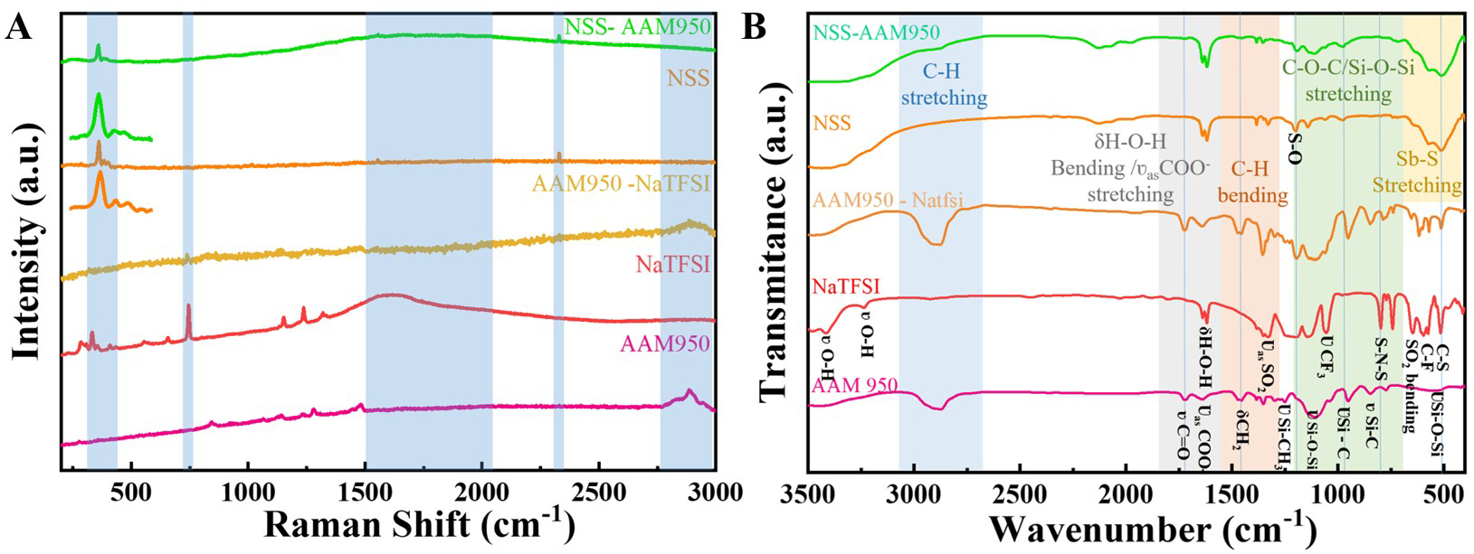
Figure 2. (A) Raman spectra (Inset: Enlarged view of 318-500 cm-1) and (B) FTIR spectra of individual AAM950 polymer components before and after coating on the NSS surface.
To further examine the interfacial interactions and chemical environment, FTIR spectra were analyzed, as shown in Figure 2B. The spectra reveal a uniform distribution of NaTFSI within the AAM950 polymer coating together with a clear interaction between the polymer and NSS surface. Pristine NaTFSI exhibits characteristic asymmetric and symmetric SO2 stretching modes of the TFSI- anion at 1,336 and 1,141 cm-1, respectively, along with CF3 stretching vibrations at 1,233 and 1,063 cm-1[33-37]. Imide S-N-S vibrations are observed at 800 and 745 cm-1[34,36,37]. In the NSS spectrum, characteristic ν(Sb-S) stretching modes of the SbS43- tetrahedra appear at 570.8 and 513.9 cm-1[33].
In addition, weak features between 1,386 and 1,067 cm-1 were attributed to slight surface oxidation during sample handling. Hydration-related bands at 1,642 and 1,617 cm-1, together with broad O-H stretching above 3,200 cm-1, indicate the presence of lattice-bound water associated with Schlippe’s salt (Na3SbS4·9H2O)[35], highlighting the sensitivity of this material. Furthermore, the AAM950 is confirmed as a silicon-based polymer with a siloxane backbone, characterized by Si-O-Si stretching near 1,100 cm-1 and Si-H vibrations at 2,160 cm-1[37]. The polymer side chains consist of poly (ethylene glycol), identified by C-O-C stretching around 1,070 cm-1 and aliphatic C-H stretching near 2,900 cm-1[22], while carboxylate groups are indicated by a band near 1,617 cm-1[22]. Upon incorporation of NaTFSI, sodium ions coordinate with ether oxygen atoms and carboxylate groups along the polymer chains, leading to broadening of the Si-O-Si band near 1,100 cm-1, which suggests strong polymer-ion interactions within the coating. Notably, the retention of Sb-S vibrations in the 514-570 cm-1 range confirms that the crystalline framework of NSS remains intact after polymer coating. Moreover, overlapping bands near 1,617 cm-1 indicate strong interfacial interactions between the inorganic NSS surface and the organic polymer layer. This interfacial coupling is expected to facilitate Na+ transport across the inorganic-organic boundary, thereby contributing to improved electrochemical performance.
To correlate these spectroscopic findings with morphological evolution, SEM analysis was performed. The SEM image of the pristine NSS pellet, as shown in Figure 3A at a 1 µm scale, reveals a porous and agglomerated morphology characterized by numerous interparticle voids. These structural features can promote localized electronic pathways and poor interfacial contact, leading to interfacial instability during electrochemical cycling. By comparison, the polymer-coated sample shown in Figure 3B exhibits a significantly denser and more homogeneous surface morphology. The porous structure and interparticle voids are effectively suppressed after coating with 7 µL of AAM950-NaTFSI polymer electrolyte. The polymer layer forms a continuous and conformal coating, as further confirmed by the corresponding optical image. This conformal coating establishes a continuous interfacial layer that can reduce direct electronic pathways while maintaining ionic transport, thereby improving interfacial stability.
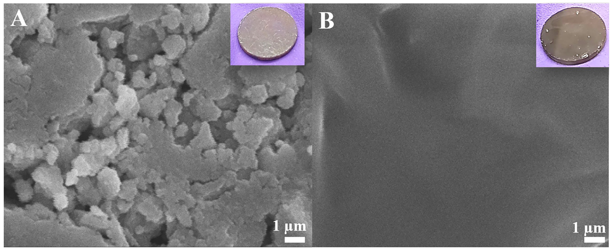
Figure 3. Top-view SEM images and corresponding optical photographs of (A) Na3SbS4 (NSS) and (B) AAM950 polymer-coated NSS pellets.
To further verify the compositional uniformity of the coating layer, SEM-EDS elemental mapping was performed as shown in Figure 4. The elemental maps of pristine NSS [Figure 4A] show uniform distributions of Na, Sb, and S, confirming the homogeneous nature of the Na3SbS4 electrolyte. After polymer coating, the sample in Figure 4B exhibits additional Na, S, and N signals originating from NaTFSI, together with Si, O, and C signals from the AAM950 polymer matrix. The homogeneous elemental distribution confirms the successful incorporation of NaTFSI within the polymer framework and its uniform coverage over the NSS surface.
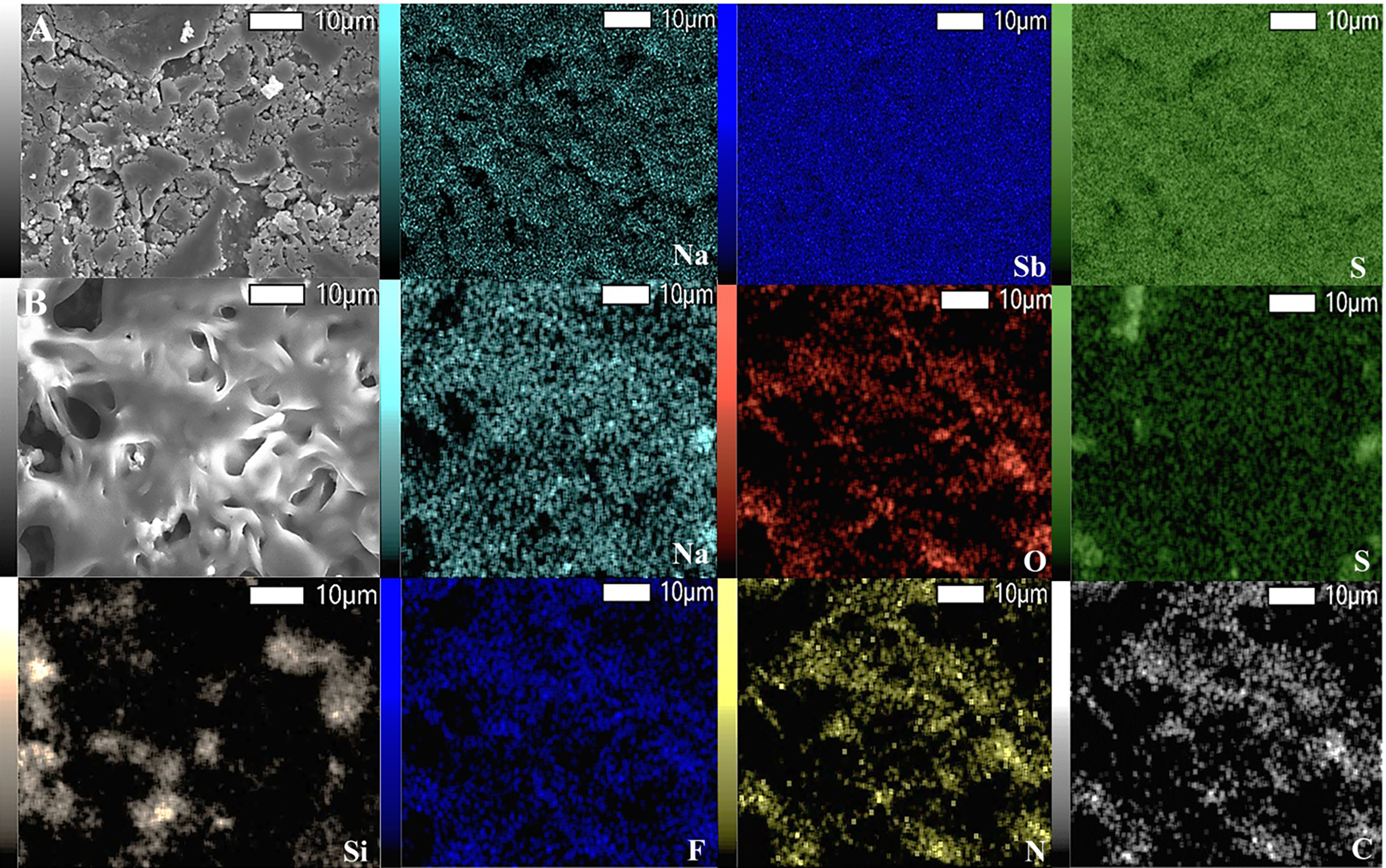
Figure 4. SEM-EDS elemental mappings of (A) pristine Na3SbS4 showing Na, Sb, and S distributions, and (B) AAM950 polymer-coated NSS showing Na, O, S, Si, F, N, and C distributions.
Electrochemical impedance spectroscopy (EIS) measurements were performed to evaluate the influence of polymer coating on ionic transport and interfacial behavior, as presented in Figure 5A (Inset: Equivalent circuit). The pristine NSS electrolyte exhibited an ionic conductivity of 3.11 × 10⁻⁴ S cm-1 at room temperature, whereas the 10 and 7 µL polymer-coated samples showed reduced ionic conductivities because of the additional polymer transport layer, as summarized in Table 1. At elevated temperature (55 °C), the overall resistance decreased substantially because of reduced polymer viscosity and enhanced segmental mobility within the polymer matrix. Among all coating conditions, the 7 µL-coated sample exhibited the lowest total resistance at 55 °C together with the highest ionic conductivity of 3.48 × 10⁻⁴ S cm-1. In contrast, the 10 µL-coated sample exhibited slightly higher resistance because the thicker polymer layer hindered Na+ transport. The Nyquist profile of the 5 µL-coated sample displayed partially separated semicircle features, suggesting incomplete polymer coverage and non-uniform electrolyte/electrode contact. Meanwhile, the
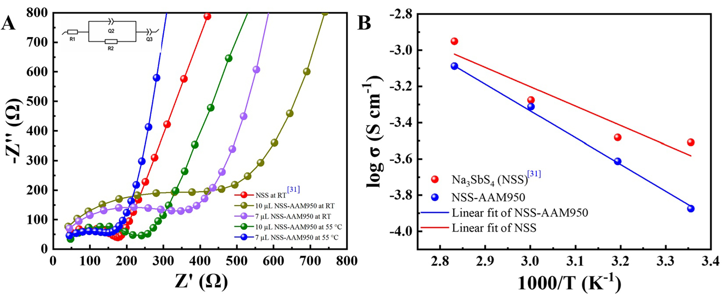
Figure 5. Electrochemical characterization of NSS electrolytes with and without polymer coating. (A) Nyquist plots of NSS pellets coated with different volumes of AAM950 polymer (Inset: Equivalent circuit). Bare NSS data were reproduced from Ref.[31] for comparison. (B) Arrhenius plots showing the temperature-dependent ionic conductivity of pristine NSS and 7 µL AAM950-coated NSS from 25 to 80 °C.
Ionic conductivity values of pristine Na3SbS4 (NSS) and NSS pellets coated with different volumes of AAM950-NaTFSI polymer electrolyte
| Sample (NSS-poly) | Rtot = (R1 + R2) (Ω) | L (µm) | Ionic conductivity (×10-3 S cm-1) |
| NSS | 175.4 | 430 | 0.31 |
| 10 µL at RT | 469.15 | 470 | 0.109 |
| 7 µL at RT | 367 | 450 | 0.156 |
| 10 µL at 55 °C | 208.6 | 470 | 0.27 |
| 7 µL at 55 °C | 172.2 | 450 | 0.348 |
The ionic conductivity of the 7 µL AAM950-NaTFSI-coated NSS increased from 1.56 × 10⁻⁴ S cm-1 at 25 °C to 8.17 × 10⁻⁴ S cm-1 at 80 °C, confirming thermally activated Na+ transport behavior, as shown in Figure 5B. For comparison, pristine NSS exhibited ionic conductivity increasing from 3.11 × 10⁻⁴ S cm-1 at 25 °C to
Symmetric Na||Na cells were subsequently evaluated through stripping/plating measurements at 0.1 mA cm-2 to investigate interfacial stability, as shown in Figure 6A. The pristine NSS electrolyte initially exhibited a low overpotential of approximately 0.025 V; however, the polarization rapidly increased to nearly 0.5 V, and the cell failed after 10 cycles. This unstable behavior reflects poor interfacial contact together with continuous interfacial degradation during repeated Na plating/stripping. The 7 µL AAM950-NaTFSI-coated NSS maintained a comparatively stable overpotential of approximately 0.08 V for more than 40 cycles. This improved electrochemical behavior suggests enhanced interfacial conformity and more uniform Na deposition enabled by the polymer interlayer. The corresponding impedance evolution during cycling is presented in Figure 6B (Inset: Equivalent circuit). The polymer-coated electrolyte maintained relatively stable impedance behavior throughout cycling, while the interfacial resistance (R3) decreased slightly from 1,500.3 to 1,357 Ω during the initial cycling process. This behavior may be associated with improved physical contact and interface wetting between Na metal and the polymer-coated electrolyte during repeated stripping/plating. Critical current density (CCD) measurements performed at 55 °C are shown in Supplementary Figure 2. For pristine NSS, the voltage profile remained relatively stable at low current density but exhibited abrupt failure at 0.65 mA cm-2, indicating internal short-circuiting caused by unstable Na deposition. In addition, the fluctuating voltage response observed at 55 °C compared with the smoother room-temperature behavior suggests intensified interfacial reactions and non-uniform Na plating at elevated temperature. Meanwhile, the 7 µL AAM950-NaTFSI-coated NSS exhibited gradual polarization increase from 0.1 to 0.9 V across the tested current-density range of 0.1-1.5 mA cm-2 without abrupt voltage collapse. This behavior indicates improved tolerance toward high-current operation together with delayed short-circuit formation arising from more homogeneous Na deposition and reduced localized current concentration.
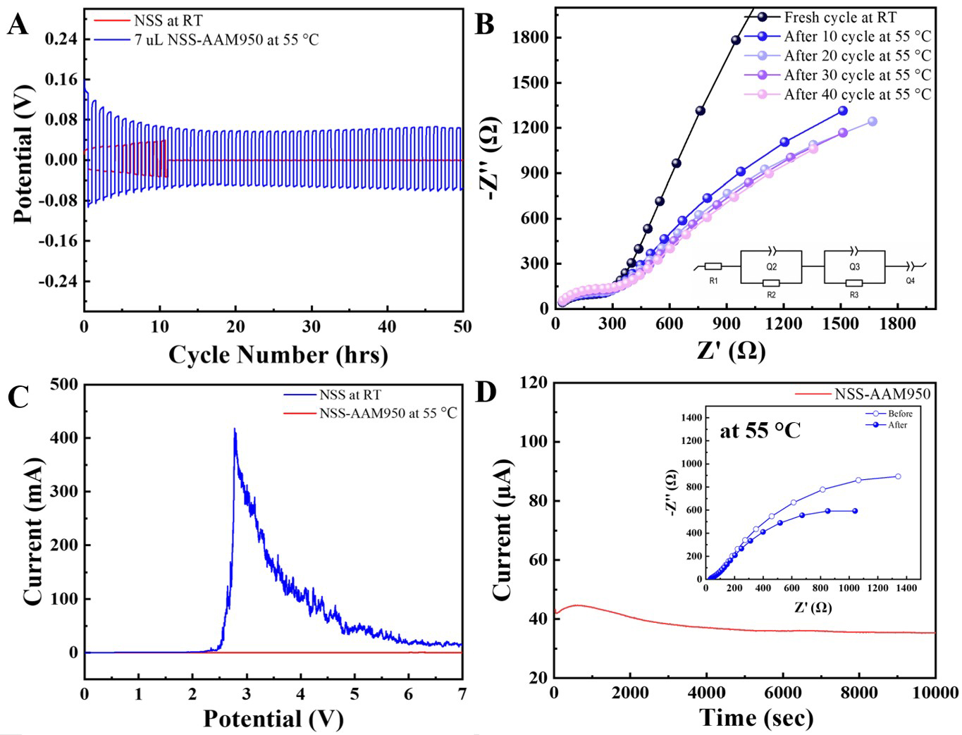
Figure 6. (A) Stripping/plating profiles at 0.1 mA cm-2 and (B) corresponding Nyquist plots of 7 µL AAM950-NSS-AAM950 at 55 °C (Inset: Equivalent circuit). (C) Linear sweep voltammetry (LSV) curves of pristine NSS at RT and 7 µL AAM950-NSS-AAM950 at 55 °C measured at 0.1 mV s-1. (D) DC polarization profile at 500 mV (Inset: Nyquist plot).
To further clarify the interfacial evolution, EIS measurements were conducted before and after CCD testing, as shown in Supplementary Figure 3 (Inset: Equivalent circuit; enlarged high-frequency region). The extracted fitting parameters are summarized in Supplementary Table 2. After CCD testing, the pristine NSS cell exhibited abnormal impedance behavior associated with internal short-circuiting and cell failure. In contrast, the polymer-coated sample retained measurable impedance behavior after cycling, although the interfacial resistance still increased because of continued interphase evolution during high-current operation. Thus, the coating does not eliminate interfacial reactions, but it slows their progression and preserves a more functional interface during high-current operation. Linear sweep voltammetry (LSV) measurements shown in Figure 6C were performed to evaluate the electrochemical behavior of the NSS electrolyte. The pristine NSS measured at room temperature exhibited a sharp increase in current near 2.6 V, indicating the onset of oxidative decomposition. The polymer-coated NSS measured at 55 °C exhibited significantly suppressed current response throughout the measured voltage range up to 7 V. Although direct comparison is limited because of the different testing temperatures, the reduced current response suggests moderated oxidative reactions under the tested conditions.
The sodium-ion transference number was calculated using Equation (3)[38],
The electrolyte properties were further evaluated through direct current polarization and impedance analysis [Figure 6D]. The 7 μL polymer-coated cell exhibited an initial current (I0) of 47.80 μA, which stabilized at
The interfacial behavior of symmetric Na||Na cells was further investigated using cyclic voltammetry over a potential range of -0.5 to 0.5 V, together with impedance analysis (Inset: Equivalent circuit), as shown in Figure 7, and the corresponding resistance values obtained from equivalent circuit fitting are presented in Table 2. For pristine NSS at room temperature [Figure 7A], the cathodic current decreased significantly from -0.139 mA in the first cycle to -0.017 mA by the fifth cycle, indicating a progressive loss of electrochemical activity caused by interfacial degradation. Correspondingly, the impedance response
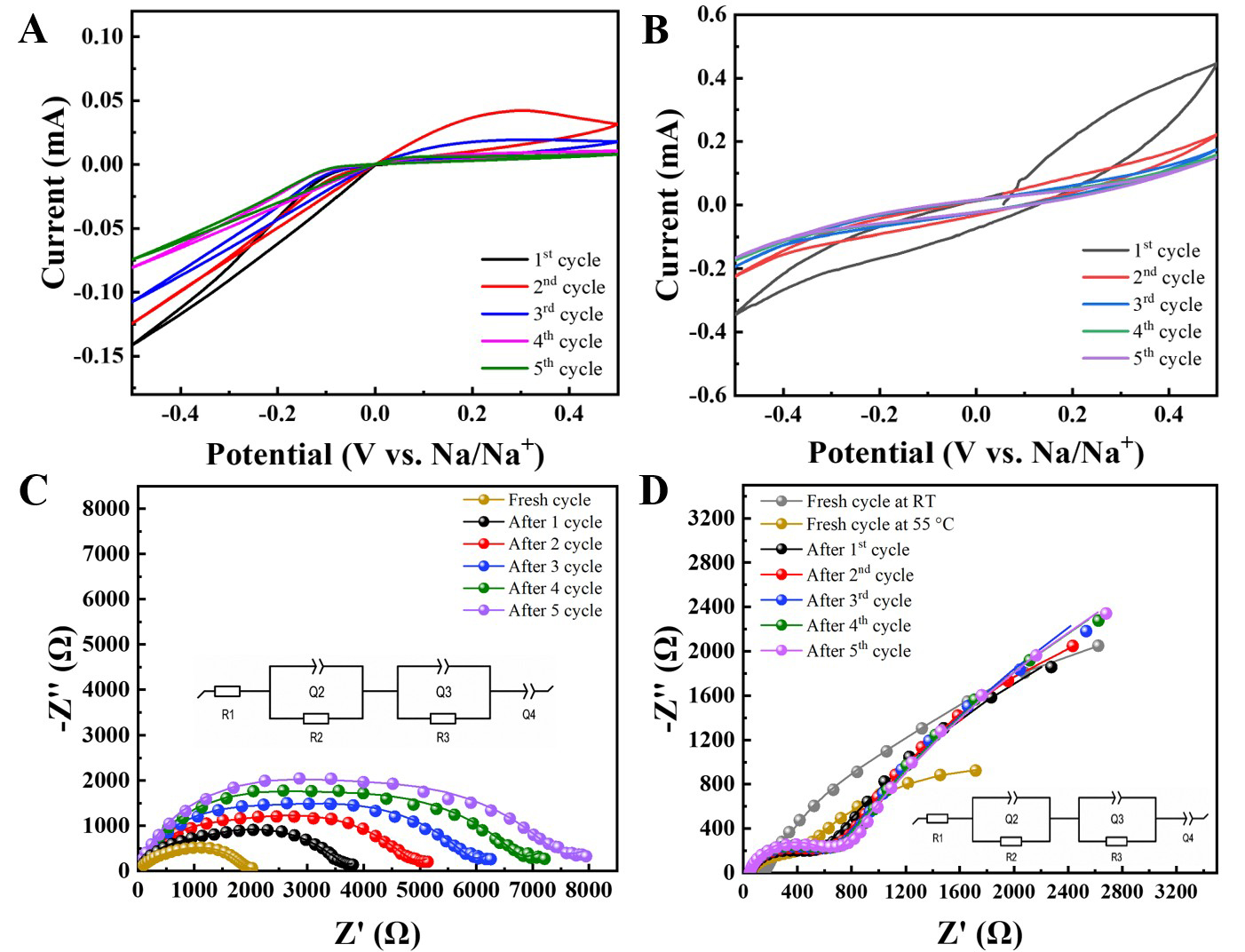
Figure 7. (A) Cyclic voltammetry and (C) Nyquist plots of pristine NSS at RT (Inset: Equivalent circuit), (B) Cyclic voltammetry and (D) Nyquist plots of 7 µL of AAM950-NSS-AAM950 at 55 °C (Inset: Equivalent circuit).
Comparison of charge-transfer resistance values derived from cyclic voltammetry measurements
| Samples | Cycle number | R1 (Ω) | R2 (Ω) | R3 (Ω) |
| NSS at RT | Fresh cycle | 32.3 | 694.31 | 1,725 |
| 1 cycle | 33.68 | 523.9 | 3,099 | |
| 2 cycle | 25 | 1,273 | 3,433 | |
| 3 cycle | 19.35 | 1,731 | 4,253 | |
| 4 cycle | 18.04 | 2,558 | 4,326 | |
| 5 cycle | 15.75 | 2,798 | 4,870 | |
| NaTFSI-AAM-NSS at 55 °C | Fresh cycle | 46.08 | 302.03 | 3,102 |
| 1 cycle | 47.77 | 409.05 | 1,623 | |
| 2 cycle | 47.23 | 506.29 | 1,062 | |
| 3 cycle | 45.94 | 519.87 | 943.33 | |
| 4 cycle | 45.97 | 549.3 | 891.03 | |
| 5 cycle | 45.38 | 555.77 | 826.75 |
Electrochemical impedance spectroscopy was further performed before cycling and after 50 cycles at 55 °C to evaluate interfacial evolution in NFMO|SE|Na cells, as shown in Figure 8A and B, with the fitted equivalent circuit presented in the inset. The high-frequency regions of Figure 8A and B are provided in
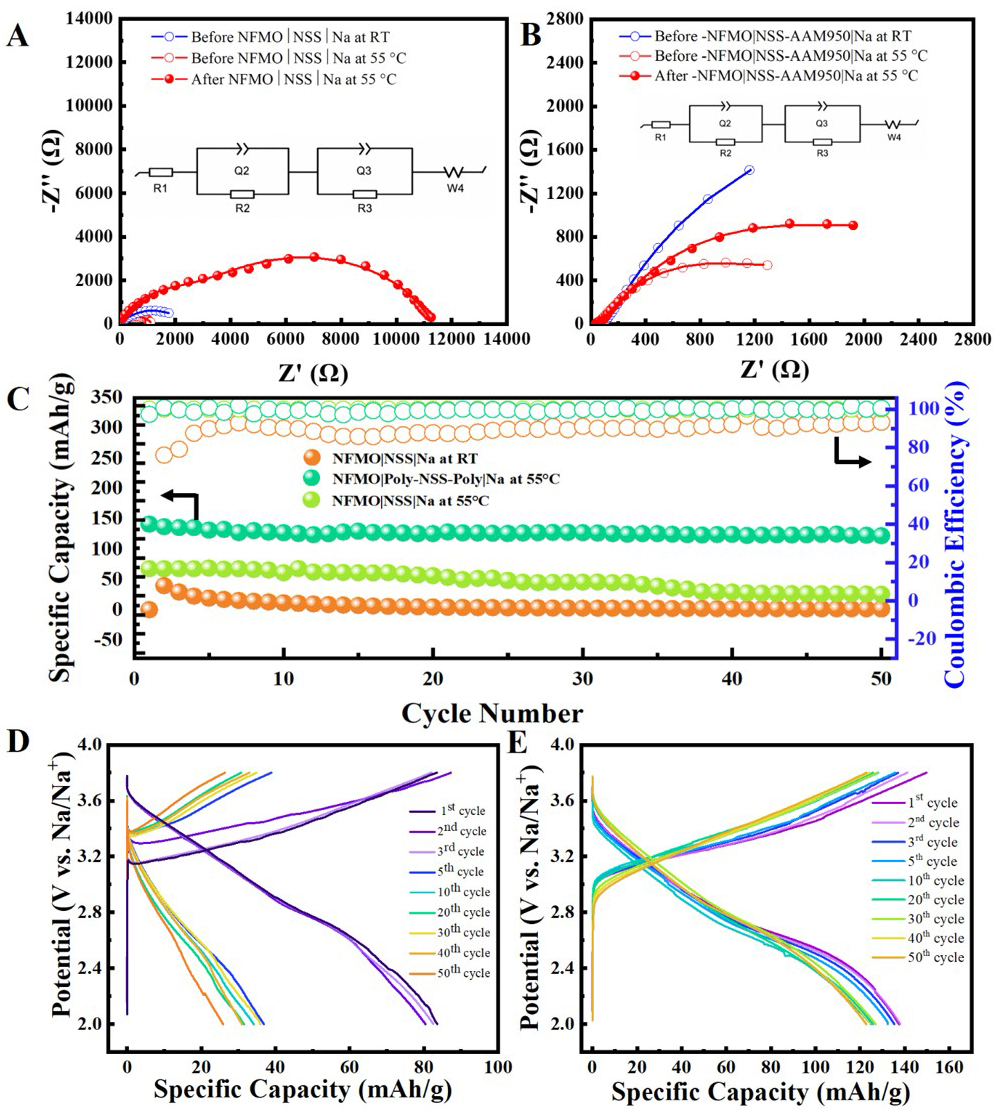
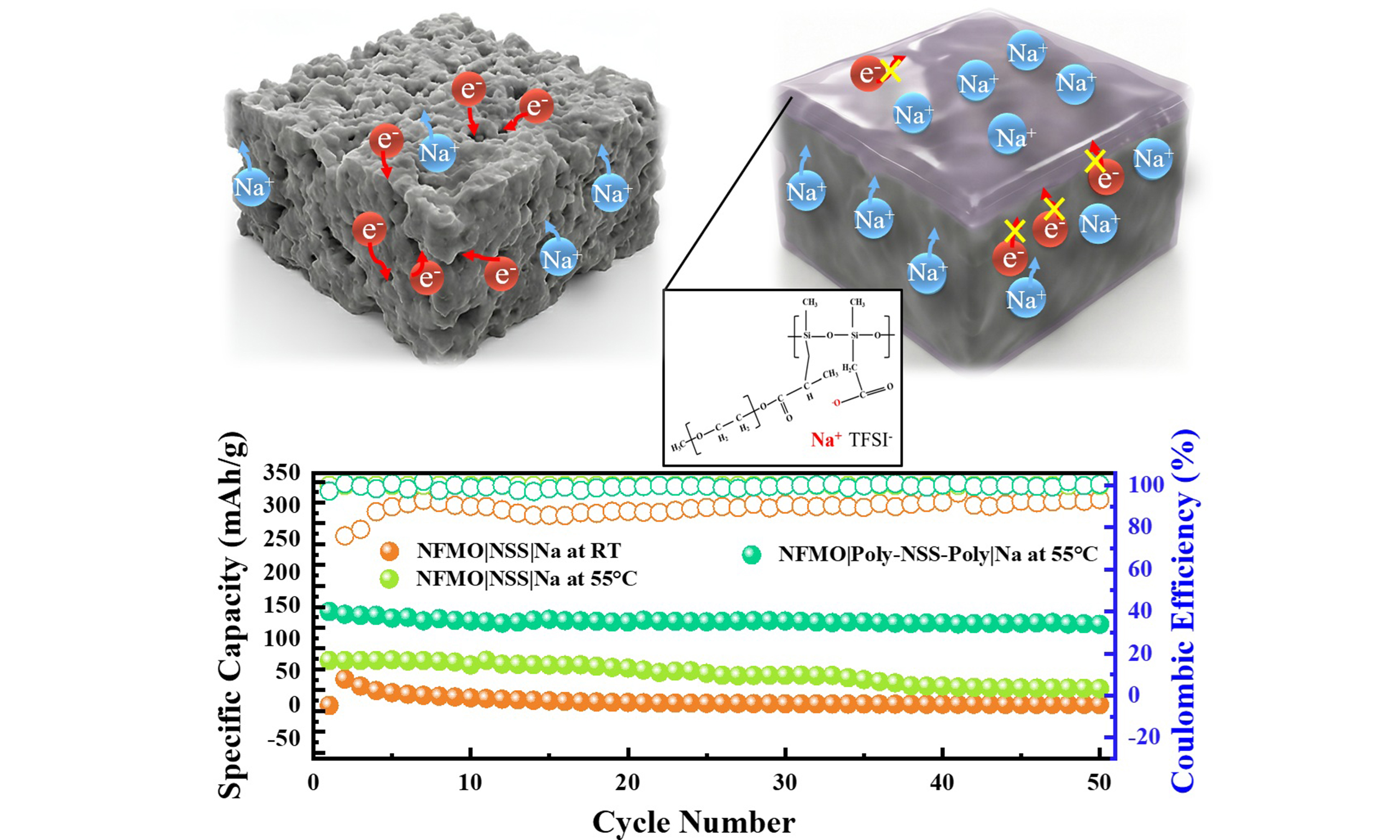
Figure 8. Nyquist impedance spectra before and after 50 electrochemical cycles of NFMO|SE|Na cells at 0.02 A g-1: (A) pristine NSS and (B) 7 µL AAM950-NSS-AAM950 at 55 °C (Inset: Equivalent circuit). (C) Cycling performance of NFMO|NSS|Na and NFMO|7 µL AAM950-NSS-AAM950|Na cells. (D and E) Corresponding galvanostatic charge/discharge profiles.
The chemical and morphological evolution of the 7 μL NaTFSI-AAM950 polymer coating on the NSS solid electrolyte is presented in Figure 9. For comparison, the polymer-coated surface shown in
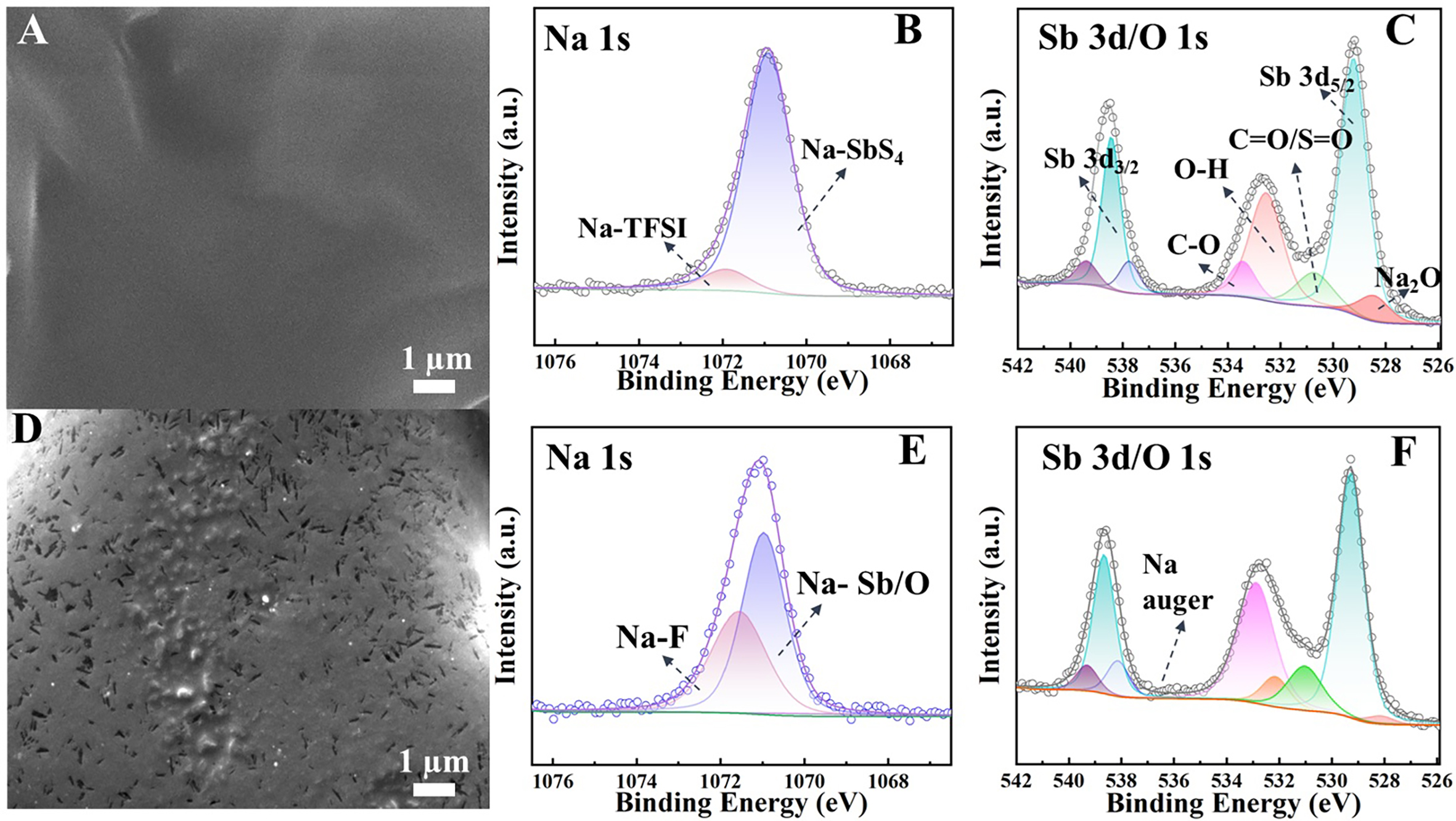
Figure 9. Top-view SEM and XPS analysis of the AAM950-coated NSS solid electrolyte before and after cycling. (A) SEM image of the polymer-coated surface is shown again for better comparison with the pristine NSS in Figure 3A. XPS spectra before cycling include (B) Na 1s and (C) Sb 3d/O 1s. After 50 electrochemical cycles, (D) top-view SEM shows the morphological evolution, while XPS spectra of (E) Na 1s and (F) Sb 3d/O 1s reveal chemical changes at the interface in the disassembled NFMO|7 µL AAM950-NSS-AAM950|Na cell tested at 55 °C.
To evaluate the interfacial morphology and chemical evolution, Figure 10 presents cross-sectional SEM images together with S 2p and F 1s XPS spectra obtained before and after cycling. The initial cross-section [Figure 10A] reveals that the 7 μL polymer layer possesses an approximate thickness of 8.7 μm and forms a continuous contact with the NSS surface. This observation suggests that the polymer is not merely a superficial coating but partially penetrates into the near-surface region of the porous electrolyte, thereby enhancing interfacial conformity. The initial S 2p spectrum [Figure 10B] shows contributions from TFSI- species at 169.0 eV and the characteristic Sb-S-Na environment at 161.2 eV. The corresponding F 1s spectrum [Figure 10C] displays a dominant C-F3 signal at 688.6 eV, confirming the presence of intact NaTFSI within the polymer layer before cycling. After 50 electrochemical cycles, the cross-sectional SEM image [Figure 10D] demonstrates that the polymer region remains structurally continuous, with features extending into the NSS structure (highlighted region). The interfacial layer remained structurally continuous throughout electrochemical cycling. In contrast, the uncoated NSS sample [Supplementary Figure 5] exhibits localized protrusion-like interfacial irregularities, indicating non-uniform interfacial evolution during cycling. This comparison highlights that the polymer-coated system promotes more homogeneous interfacial contact during electrochemical operation. The post-cycling S 2p spectrum [Figure 10E] reveals the emergence of additional sulfur-containing species, including oxidized components (SO42-/SO42-)[39] at
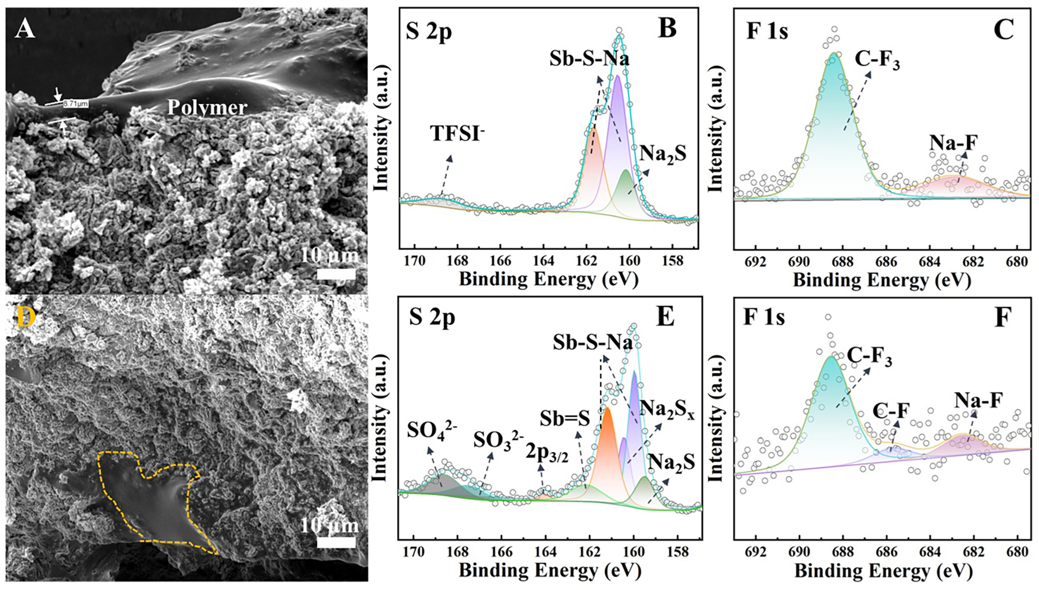
Figure 10. Cross-sectional SEM images and XPS spectra of the 7 µL AAM950-coated NSS electrolyte before and after electrochemical cycling. (A) Cross-sectional SEM image before cycling and (D) after 50 cycles. (B and C) S 2p and F 1s spectra before cycling. (E and F) S 2p and F 1s spectra after 50 cycles obtained from disassembled NFMO|7 µL AAM950-NSS-AAM950|Na cells operated at 55 °C.
The interfacial mechanism of the 7 μL AAM950-NaTFSI polymer coating on the Na3SbS4 solid electrolyte is illustrated in Figure 11. As shown in Figure 11A, direct contact between bare Na3SbS4 and sodium metal may induce interfacial reactions, leading to the formation of Na-Sb species, Na2S, and Sb-related products that can contribute to electronic leakage and interfacial instability[27]. These processes are further associated with non-uniform Na deposition and localized penetration into the porous electrolyte structure. By comparison, Figure 11B illustrates that the polymer coating functions as an artificial interfacial layer that partially fills surface pores and improves physical contact at the electrolyte/electrode interface. Consequently, localized Na penetration into the porous structure is reduced, and more uniform Na+ transport is promoted, consistent with the enhanced cycling stability observed in this study. XPS analysis further suggests the formation of interfacial species such as Na2O, NaF, and Na2S during cycling. However, the current evidence remains indirect, and therefore, the formation of a fully stabilized solid electrolyte interphase (SEI) is inferred rather than directly confirmed.
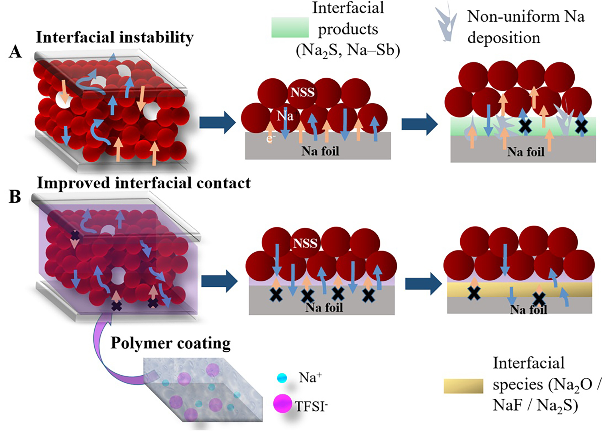
Figure 11. Schematic illustration of interfacial evolution in NSS electrolytes with and without polymer coating during cycling.
At the operating temperature of 55 °C, the polymer matrix exhibits reduced viscosity, thereby facilitating Na+ transport across the interface and supporting stable electrochemical performance under the tested conditions. Overall, the improved electrochemical behavior is mainly associated with stabilized interfacial contact and moderated interfacial degradation enabled by the polymer layer.
The Na||NFMO cell employing the AAM950-coated NSS electrolyte delivered moderate specific capacities within the operating voltage window of the NFMO cathode (2.0-3.8 V). Direct comparison with previously reported systems employing FeS2 or TiS2 cathodes should be interpreted cautiously because those cathode materials typically operate within lower voltage ranges (e.g., 0.9-2.5 V), which can result in higher charge capacities under similar current conditions. To ensure a fair comparison, the current densities reported in the literature were recalculated to A g-1 based on the electrode thickness and mass loading provided in the original studies. As summarized in Figure 12 and Table 3[21,25,28,29,42,43], the AAM950-coated NSS system demonstrates competitive performance relative to prior reports, particularly when considering its operation at a higher voltage window.
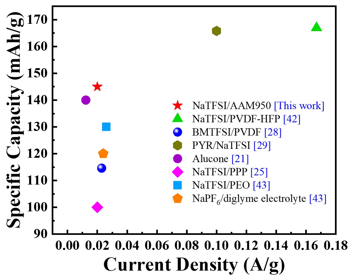
Figure 12. Comparison of charge capacities reported for Na3SbS4-based solid electrolytes with various surface-coating strategies from the literature and present work (AAM950/NaTFSI). Current densities were unified in A g-1 for consistent evaluation.
Comparison of the electrochemical performance of the present AAM950-coated NSS system with previously reported sodium all-solid-state battery systems
| Polymer on Na3SbS4 pellet | Electrodes | Current density (mA g-1) | Charge capacity (mAh g-1) | Cycle number/°C | References |
| NaTFSI/AAM950 | NFMO/Na | *0.02 | 149.7 | 50/55 | This work |
| NaTFSI/PVDF-HFP | #TiS2/Na | $1 | 167 | 100/RT | [42] |
| PVDF-0.2IL BMTFSI | NVP/Na | $0.2 | 114.6 | 400/50 | [28] |
| (PYR/Na)TFSI | FeS2/Na | 100 | 165.8 | 300/RT | [29] |
| Alucone | #TiS2/Na-mld 150C | &0.11 | 140 | 30/RT | [21] |
| PPP/NaTFSI | TiS2/Na | 20 | 100 | 300/50 | [25] |
| PEO/NaTFSI | PTCDA/Na | $0.2 | 130 | 200/45 | [43] |
| 1M NaPF6/diglyme electrolyte | PTCDA/ Na | $0.2 | 120 | 60/RT | [43] |
CONCLUSIONS
An artificial interfacial layer based on a 7 μL AAM950-NaTFSI polymer coating was successfully introduced onto the Na3SbS4 solid electrolyte to mitigate interfacial instability associated with sulfide electrolyte decomposition and non-uniform Na deposition. The conformal polymer layer partially filled surface pores and improved solid-solid contact at the electrode/electrolyte interface, leading to more stable electrochemical behavior during cycling. Although the polymer coating did not significantly enhance the intrinsic bulk ionic conductivity of NSS, it effectively stabilized the interfacial region and reduced localized degradation during repeated Na plating/stripping. As a result, the polymer-modified system delivered a discharge capacity of
DECLARATIONS
Authors’ contributions
Paper writing and experimental, data analysis: Thairiyarayar, C. B.
Polymer preparation and review: Wang, F. M.
Normal analyses: Kheawhom, S.; Chang, J. K.
Core idea, data analysis, and Supervision: Liu, W. R.
Availability of data and materials
The original contributions presented in this study are included in the article/Supplementary Materials. Further inquiries can be directed to the corresponding author(s).
AI and AI-assisted tools Statement
During the preparation of this manuscript, the AI tools ChatGPT Plus (OpenAI), Grammarly Free, and Nano Banna AI Pro were used solely for language editing, proofreading, and visualization enhancement. Nano Banna AI Pro was used to improve image clarity and convert SEM images into 3D visualizations for the Table of Contents graphic. ChatGPT Plus was used for language refinement and sentence rephrasing, including improvement of the polymer-related discussion, while Grammarly Free was used for grammar correction and proofreading. These tools did not influence the study design, data collection, analysis, interpretation, or the scientific content of the work. All authors take full responsibility for the accuracy, integrity, and final content of the manuscript.
Financial support and sponsorship
The authors gratefully acknowledged the National Science and Technology Council (NSTC) project grant no. NSTC 114-2221-E-033-008, 113-2218-E-007-015, 114-2923-E-033 -001-MY3, 113-2622-E-033-003, 113-2923-E-006-002, 113-2112-M-008 -033 and 114-2112-M-008-026. The authors also appreciate the financial support from CYCU-WIArk-250CH (Wisdom Innovation Ark).
Conflicts of interest
All authors declared that there are no conflicts of interest.
Ethical approval and consent to participate
Not applicable.
Consent for publication
Not applicable.
Copyright
© The Author(s) 2026.
Supplementary Materials
REFERENCES
1. Li, Z.; Zhang, Y.; Bai, J.; Wang, J.; Zhao, H. Well-dispersed FeP@C nanoparticles anchored on MXene conductive network as outstanding cyclic performance anode for Li/Na-ion batteries. Carbon 2025, 234, 120008.
2. Liu, C.; Zhang, Z.; Liao, H.; et al. Unlocking the potential: Na4Fe3(PO4)2(P2O7) supporting the innovation of commercial sodium‐ion batteries. Adv. Funct. Mater. 2025, 35, 2424759.
3. Zhao, L.; Zhang, T.; Li, W.; et al. Engineering of sodium-ion batteries: opportunities and challenges. Engineering 2023, 24, 172-83.
4. Yu, Z.; Shang, S. L.; Seo, J. H.; et al. Exceptionally high ionic conductivity in Na3P0.62As0.38S4 with improved moisture stability for solid‐state sodium‐ion batteries. Adv. Mater. 2017, 29, 1605561.
5. Tsuji, F.; Nasu, A.; Hotehama, C.; Sakuda, A.; Tatsumisago, M.; Hayashi, A. Preparation and characterization of sodium-ion conductive Na3BS3 glass and glass-ceramic electrolytes. Mater. Adv. 2021, 2, 1676-82.
6. Takeuchi, S.; Suzuki, K.; Hirayama, M.; Kanno, R. Sodium superionic conduction in tetragonal Na3PS4. J. Solid. State. Chem. 2018, 265, 353-8.
7. Zhang, D.; Cao, X.; Xu, D.; et al. Synthesis of cubic Na3SbS4 solid electrolyte with enhanced ion transport for all-solid-state sodium-ion batteries. Electrochim. Acta. 2018, 259, 100-9.
8. Huang, J.; Wu, K.; Xu, G.; Wu, M.; Dou, S.; Wu, C. Recent progress and strategic perspectives of inorganic solid electrolytes: fundamentals, modifications, and applications in sodium metal batteries. Chem. Soc. Rev. 2023, 52, 4933-95.
9. Matios, E.; Wang, H.; Wang, C.; Li, W. Enabling safe sodium metal batteries by solid electrolyte interphase engineering: a review. Ind. Eng. Chem. Res. 2019, 58, 9758-80.
10. Singh, R.; Tushar; Sasikumar Kala, V.; et al. Unveiling the importance of solid-liquid interphase for the development of all solid‐state sodium metal batteries. Batter. Supercaps. 2025, 8, e202500408.
11. Lacivita, V.; Wang, Y.; Bo, S.; Ceder, G. Ab initio investigation of the stability of electrolyte/electrode interfaces in all-solid-state Na batteries. J. Mater. Chem. A. 2019, 7, 8144-55.
12. Wu, M.; Liu, H.; Qi, X.; et al. Structure designing, interface engineering, and application prospects for sodium‐ion inorganic solid electrolytes. InfoMat 2024, 6, e12606.
13. Wenzel, S.; Leichtweiss, T.; Weber, D. A.; Sann, J.; Zeier, W. G.; Janek, J. Interfacial reactivity benchmarking of the sodium ion conductors Na3PS4 and sodium β-alumina for protected sodium metal anodes and sodium all-solid-state batteries. ACS. Appl. Mater. Interfaces. 2016, 8, 28216-24.
14. Xie, G.; Tang, M.; Xu, S.; Brown, A.; Sang, L. Degradation at the Na3SbS4/anode interface in an operating all-solid-state sodium battery. ACS. Appl. Mater. Interfaces. 2022, 14, 48705-14.
15. Tian, Y.; Sun, Y.; Hannah, D. C.; et al. Reactivity-guided interface design in na metal solid-state batteries. Joule 2019, 3, 1037-50.
16. Moeez, I.; Susanto, D.; Chang, W.; Lim, H.; Chung, K. Y. Artificial cathode electrolyte interphase by functional additives toward long-life sodium-ion batteries. Chem. Eng. J. 2021, 425, 130547.
17. Moorthy, M.; Thangavel, R.; Krishnan Ganesan, B.; Saha, A.; Hong, S.; Lee, Y. Ultra-high areal capacity, ultra-long life, dendrite-free sodium metal anode enabled by antimony-based Na-ion conducting artificial SEI layers. Chem. Eng. J. 2024, 498, 155234.
18. Yihao, G. U. O.; Xiaoyu, H. U.; Yongfeng, Y. U. A. N. Dual-site doping of tungsten and fluorine enhances the interface stability of Na3SbS4 in all-solid-state sodium metal batteries. J. Mater. Sci. 2025, 43, 1673-2812.
19. Wang, L.; Liu, G.; Li, Y.; Weng, W.; Xin, X.; Yao, X. Tungsten and boron codoping toward high ionic conductivity and stable sodium solid electrolyte for all-solid-state sodium batteries. ACS. Appl. Mater. Interfaces. 2024, 16, 4847-53.
20. Zhang, Z.; Cao, H.; Zhang, L. Preparation and electrochemical properties of ionic-liquid-modified Na3SbS4 membrane composite electrolytes. J. Mater. Sci. 2021, 56, 10565-74.
21. Zhang, S.; Zhao, Y.; Zhao, F.; et al. Gradiently sodiated alucone as an interfacial stabilizing strategy for solid-state Na metal batteries. Adv. Funct. Mater. 2020, 30, 2001118.
22. Ren, Y.; Hortance, N.; Mcbride, J.; Hatzell, K. B. Sodium-Sulfur batteries enabled by a protected inorganic/organic hybrid solid electrolyte. ACS. Energy. Lett. 2020, 6, 345-53.
23. Wang, T.; Yu, Q.; Li, Z.; et al. The potential of solid‐state potassium‐ion batteries with polymer‐based electrolytes. Carbon. Energy. 2025, 7, e670.
24. Chen, S.; Che, H.; Feng, F.; et al. Poly(vinylene carbonate)-based composite polymer electrolyte with enhanced interfacial stability to realize high-performance room-temperature solid-state sodium batteries. ACS. Appl. Mater. Interfaces. 2019, 11, 43056-65.
25. Li, Y.; Arnold, W.; Halacoglu, S.; Jasinski, J. B.; Druffel, T.; Wang, H. Phase‐transition interlayer enables high‐performance solid‐state sodium batteries with sulfide solid electrolyte. Adv. Funct. Mater. 2021, 31, 2101636.
26. Zhang, Y.; Hu, P.; Yao, Y. Polymer-sulfide composite solid state electrolyte with enhanced interfacial stability with sodium metal. Meet. Abstr. 2017, MA2017-01, 559.
27. Hu, P.; Zhang, Y.; Chi, X.; et al. Stabilizing the interface between sodium metal anode and sulfide-based solid-state electrolyte with an electron-blocking interlayer. ACS. Appl. Mater. Interfaces. 2019, 11, 9672-8.
28. Wang, Z.; Zhang, L.; Shang, X.; et al. Enhanced electrochemical performance enabled by ionic-liquid-coated Na3SbS4 electrolyte encapsulated in flexible filtration membrane. Chem. Eng. J. 2022, 428, 132094.
29. Li, Y.; Halacoglu, S.; Shreyas, V.; et al. Highly efficient interface stabilization for ambient-temperature quasi-solid-state sodium metal batteries. Chem. Eng. J. 2022, 434, 134679.
30. Wang, F.; Wan, C.; Wang, Y. Synthesis of functionalized copolymer electrolytes based on polysiloxane and analysis of their conductivity. J. Appl. Electrochem. 2008, 39, 253-60.
31. Thairiyarayar, C. B.; Huang, C.; Gandomi, Y. A.; Hsieh, C.; Liu, W. Synthesis and characterization of Na3SbS4 solid electrolytes via mechanochemical and sintered solid-state reactions: a comparative study. Sustainability 2023, 15, 15662.
32. Wang, H.; Chen, Y.; Hood, Z. D.; et al. An air-stable Na3SbS4 superionic conductor prepared by a rapid and economic synthetic procedure. Angew. Chem. Int. Ed. 2016, 128, 8693-7.
33. Tang, B.; Zhao, Y.; Wang, Z.; et al. Ultrathin salt-free polymer-in-ceramic electrolyte for solid-state sodium batteries. eScience 2021, 1, 194-202.
34. Kmiec, S.; Ruoff, E.; Darga, J.; Bodratti, A.; Manthiram, A. Scalable glass-fiber-polymer composite solid electrolytes for solid-state sodium-metal batteries. ACS. Appl. Mater. Interfaces. 2023, 15, 20946-57.
35. Mikenda, W.; Preisinger, A. Vibrational spectra of Na3SbS4, Na3SbS4·9H2O (Schlippe's salt) and Na3SbS4·9D2O. Spectrochim. Acta. A. Mol. Biomol. Spectrosc. 1980, 36, 365-70.
36. Noor, S.; Su, N.; Khoon, L.; et al. Properties of high Na-ion content N-propyl-N-methylpyrrolidinium bis(fluorosulfonyl)imide -ethylene carbonate electrolytes. Electrochim. Acta. 2017, 247, 983-93.
37. Khurana, S.; Chandra, A. Ionic liquid‐based organic-inorganic hybrid electrolytes: impact of in situ obtained and dispersed silica. J. Polym. Sci. B. Polym. Phys. 2017, 56, 207-18.
38. Wang, W.; Ding, M.; Chen, S.; et al. A novel composite solid electrolyte with ultrahigh ion transference number and stability for solid-state sodium metal batteries. Chem. Eng. J. 2024, 491, 151989.
39. Liu, Y.; Lu, S.; Weng, S.; et al. Interphase‐regulated room‐temperature sodium‐sulfur batteries enabled by a nonflammable dual‐functional electrolyte. Adv. Energy. Mater. 2024, 15, 2404890.
40. Eshetu, G. G.; Diemant, T.; Hekmatfar, M.; et al. Impact of the electrolyte salt anion on the solid electrolyte interphase formation in sodium ion batteries. Nano. Energy. 2019, 55, 327-40.
41. Miao, Y.; Lin, D.; Liu, J.; et al. A non-fluorinated, weakly solvating electrolyte for efficient sodium-sulfurized polyacrylonitrile batteries. J. Mater. Chem. A. 2025, 13, 17479-88.
42. Mwemezi, M.; Park, W. B.; Ikhe, A. B. Improvement of interfacial stability between Na metal and Na3PS4 family solid electrolyte for all-solid-state sodium metal batteries. Electrochim. Acta. 2024, 480, 143919.
Cite This Article
How to Cite
Download Citation
Export Citation File:
Type of Import
Tips on Downloading Citation
Citation Manager File Format
Type of Import
Direct Import: When the Direct Import option is selected (the default state), a dialogue box will give you the option to Save or Open the downloaded citation data. Choosing Open will either launch your citation manager or give you a choice of applications with which to use the metadata. The Save option saves the file locally for later use.
Indirect Import: When the Indirect Import option is selected, the metadata is displayed and may be copied and pasted as needed.
About This Article
Copyright

Data & Comments
Data
0


Comments
Comments must be written in English. Spam, offensive content, impersonation, and private information will not be permitted. If any comment is reported and identified as inappropriate content by OAE staff, the comment will be removed without notice. If you have any queries or need any help, please contact us at [email protected].