

fig2
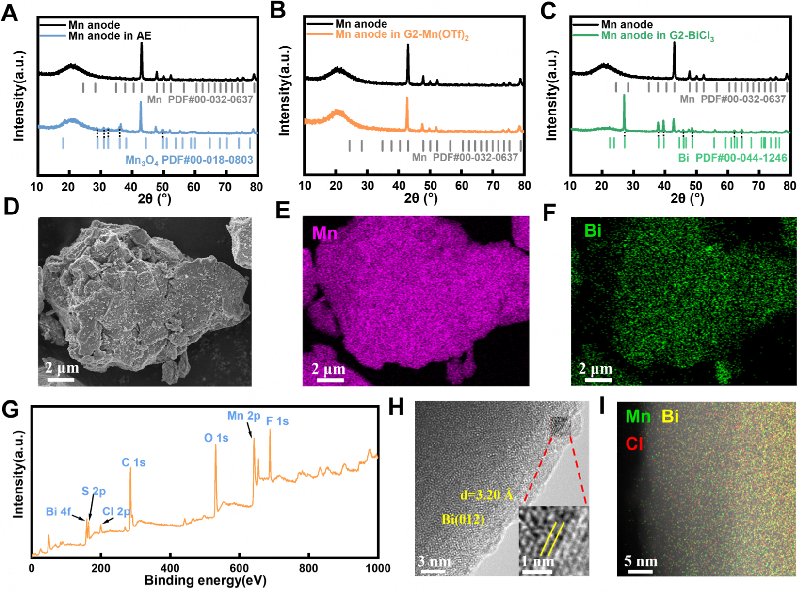
Figure 2. (A-C) XRD patterns of Mn anodes treated with different electrolytes; (D) SEM image and (E), (F) corresponding Mn and Bi EDS elemental mappings of Mn powder immersed in the G2-BiCl3 electrolyte; (G) XPS survey spectrum of the Mn anode after immersion in the G2-BiCl3 electrolyte; (H) TEM image and (I) corresponding EDS elemental mapping of the Bi-containing interphase on the immersed Mn anode.