

fig1
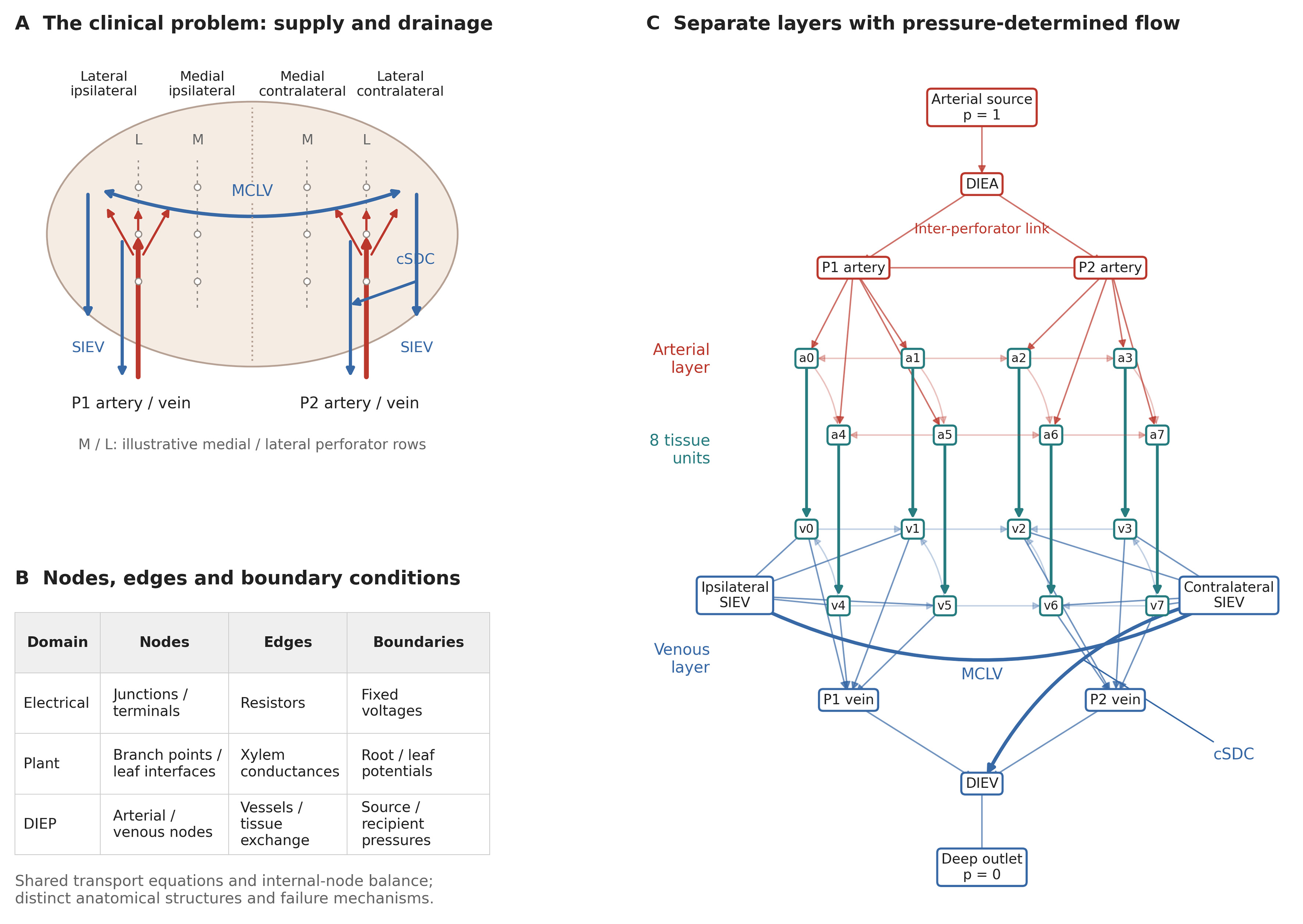
Figure 1. Clinical problem and compartmental model. (A) Idealized lower abdominal flap illustrating medial and lateral perforator rows, ipsilateral and contralateral tissue territories, perforator supply, superficial collectors, MCLV and cSDC. Territory labels indicate relative location, not a numbered perfusion-zone scheme or measured perforasomes; rows and pathway positions are schematic; (B) Mapping of nodes, edges and boundary conditions across resistive electrical networks, plant hydraulics and the DIEP model. Tissue units exchange flow and drain to veins; they are not terminal leaves; (C) Exact eight-unit enhanced reference graph (26 nodes, 61 edges). Red denotes arterial pathways, blue venous pathways and teal tissue exchange. Each ai/vi pair is one tissue unit. Arrows follow the solved pressure gradient; zero-flow connections are shown without arrows. Lighter lines indicate local collaterals. SIEVs are internal collectors in this deep-only configuration. The cSDC is contralateral. DIEV: Deep inferior epigastric vein; SIEV: superficial inferior epigastric vein; MCLV: midline-crossing linking vein; cSDC: contralateral superficial-to-deep connection; DIEP: deep inferior epigastric perforator.