


The effect of natural convection on the dendritic tip stability during directional solidification: insights from phase-field-lattice Boltzmann simulations
 0
0 Abstract
In this paper, the effect of natural convection on the stability of the dendritic tip during directional solidification under various gravitational field conditions is numerically investigated using the phase-field lattice-Boltzmann method. The coupled equations were implemented for parallel computing on multi-graphics processing units using in-house code written in modular Compute Unified Device Architecture. In the single-crystal case, downward buoyancy transports solute from the dendrite roots toward the tips, leading to solute enrichment near the tips. This enrichment reduces the local undercooling, slows dendrite growth, and eventually triggers tip splitting at high convection intensities. In contrast, the upward buoyancy moves rejected solutes from tips to interdendritic regions, barely affecting solute distribution along the crystal symmetry axis and stabilizing tips. In bi-crystalline systems, downward convection induces tip splitting and plume formation in converging grain boundaries, and drives solute flow to promote sidebranching in diverging grain boundaries, while upward convection has a negligible impact on grain boundaries. This work offers quantitative insights into the dynamic mechanism by which natural convection regulates dendritic tip stability, thereby elucidating the role of natural convection in microstructure evolution during directional solidification.
Keywords
INTRODUCTION
Nickel (Ni)-based superalloys have been extensively employed in critical hot-section components such as turbine blades of aero-engines and industrial gas turbines due to their exceptional high-temperature mechanical properties and superior corrosion resistance[1,2]. The service performance of these components is largely dictated by the microstructure formed during casting, which is strongly influenced by dendritic growth behavior and its coupling with solutal convection during solidification[3,4]. Under terrestrial gravity, local density variations arising from temperature and solute gradients drive natural convection, which not only alters the morphology and distribution of dendrites but also profoundly affects dendrite arm spacing and elemental segregation[5,6]. Such thermosolutal coupling-induced disturbances often trigger severe solidification defects, such as freckles, which undermine the mechanical integrity of the material and shorten the service life of components[7,8]. Therefore, the fundamental understanding of the effect of natural convection on the dendritic growth dynamics mechanisms during directional solidification is of great engineering and theoretical significance for mitigating microstructural defects in turbine blade casting.
During directional solidification, the dendritic growth behavior and solute distribution characteristics of multicomponent high-temperature alloys are significantly influenced by processing parameters such as the thermal gradient and pulling velocity[5,9]. Previous studies demonstrated that for relatively low thermal gradient and pulling velocity, the solutal-driven natural convection leads to the formation of solutal plumes, and subsequently induces classic solidification defects such as freckles[10]. With the continued advancement of synchrotron X-ray imaging technologies, in-situ observation of dendrite growth during solidification of alloys has become increasingly feasible[11-14]. For instance, Shevchenko et al.[15,16] employed X-ray microscopy to investigate the directional solidification of Ga-In alloys, revealing that natural convection induced by density differences between Ga and In leads to solutal plumes, which in turn generate segregation channels and initiate freckle formation. Ruvalcaba et al.[17] utilized synchrotron radiation to observe dendrite fragmentation in Al-Cu alloys, which is attributed to localized solute enrichment during directional solidification. Furthermore, Reinhart et al.[18] investigated the solidification behavior of high-temperature nickel-based single crystal alloy CMSX-4 using synchrotron X-ray techniques. They reported that solute convection markedly influences dendrite growth velocity, with dendritic fragmentation occurring during the final solidification of residual liquid. These experimental findings consistently demonstrate the prevalence of solutal plumes, dendrite remelting, and overgrowth phenomena during alloy solidification. However, it is still quite challenging to deeply reveal the effect of convection on the dendritic growth mechanism in directional solidification of nickel-based superalloys by experimental means.
With the continuous advancement of computational technologies, numerical simulation has gradually emerged as a critical approach for investigating alloy solidification processes. In parallel with physics-based modeling, machine learning techniques have also been increasingly explored to assist in microstructure characterization and process-property correlation in metallic systems, benefiting from their ability to handle complex, high-dimensional datasets[19,20]. Nevertheless, a mechanistic understanding of microstructural evolution under coupled thermosolutal convection still relies predominantly on physically grounded numerical frameworks. As a widely accepted and accurate numerical method, the phase-field method that recovers the Gibbs-Thomson effect with high accuracy can simulate the evolution of complicated phase change microstructures. In the phase-field method, the interface tracking of the complex dendritic contour can be avoided by introducing the phase-field variable φ that smoothly but sharply varies from -1 (liquid phase) to 1 (solid phase). By treating the melt as an incompressible fluid flow, incorporating the Navier-Stokes (N-S) equations into the phase-field method is a direct and conventional approach for investigating the effect of convection on dendritic growth during solidification[21-23]. However, N-S solvers, which are typically based on global schemes such as finite element or finite difference methods, often suffer from low computational efficiency and numerical instability, particularly in regions with high solid fraction[24].
In recent years, the lattice Boltzmann method (LBM) has emerged as an alternative computational tool to predict the fluid flow in the melt by streaming and collision of a collection of pseudoparticles[25]. The first phase-field lattice-Boltzmann (PF-LBM) scheme was adopted by Miller et al.[26,27]. Subsequently, numerous attempts that combine the phase-field method and the LBM have been carried out to effectively simulate the dendritic growth during solidification of alloys under forced and natural convection[28,29]. For instance,
Despite significant advancements in experimental and numerical investigations, the dynamic mechanism through which natural convection affects the stability of the dendritic tip during directional solidification is unclear. Herein, a quantitative multi-order parameter phase-field model is coupled with the LBM to simulate dendritic growth under natural convection during directional solidification of a multicomponent alloy. A pseudo-binary approximation is employed, with a specific focus on the morphological instability of dendritic tips coupled with solute transport behavior under varying gravitational accelerations. Section "MATHEMATICAL MODEL" provides a concise mathematical description of the pseudo-binary approximation, the phase-field model and the LBM. We present results and discussion in Section "RESULTS AND DISCUSSION". In Section "CONCLUSIONS", conclusions from numerical simulations are presented.
MATHEMATICAL MODEL
In this paper, we adopt the quantitative multi-order parameter phase-field model proposed by Yang et al.[41] to investigate dendritic growth during directional solidification. Here, we focus on the directional solidification of the Ni-based superalloy CMSX-4. A pseudo-binary approximation is employed to simplify the multi-component superalloy. The CMSX-4 alloy can be treated as eight Ni-X binary alloys (Cr 6.5 wt.%, Mo 0.6 wt.%, Ti 1 wt.%, W 6.4 wt.%, Co 9.6 wt.%, Al 5.6 wt.%, Ta 6.5 wt.%[42]), and further reduced to an equivalent Ni-X binary alloy. Hence, the corresponding equivalent mass fractions c0, the liquidus slope m, partition coefficient k, and solutal partition coefficient βc are determined using[43]
where i is the physical properties in the i-th binary system, and N is the number of elements in the alloys. Table 1 lists chemical composition, slopes of liquidus, partition coefficients, and solutal expansion coefficients of the elements in CMSX-4. Hence, in this paper, c0 = 38.2 wt.%, m = 1.7023 K/wt.%, k = 0.688,
Chemical composition, slopes of liquidus, partition coefficients, and solutal expansion coefficients of the elements in CMSX-4
| Element | CMSX-4 composition (wt.%) | Slope of liquidus (K/wt.%) | Partition coefficient | Solutal expansion coefficient (wt.%-1) |
| Cr | 6.5 | -2.15 | 0.95 | 1.90 × 10⁻³ |
| Mo | 0.6 | -5.72 | 1.06 | -1.80 × 10⁻³ |
| Ti | 1 | -16.30 | 0.71 | 8.20 × 10⁻³ |
| W | 6.4 | 2.45 | 1.28 | -5.30 × 10⁻³ |
| Co | 9.6 | 0.01 | 1.08 | 1.13 × 10⁻⁴ |
| Al | 5.6 | -5.35 | 0.91 | 2.50 × 10⁻² |
| Ta | 6.5 | -5.00 | 0.78 | -4.60 × 10⁻³ |
| Re | 3.0 | 5.45 | 1.73 | -5.46 × 10⁻³ |
| Reference(s) | [42] | [44-46] | [47-50] | [48,49] |
In this model, the phase-field variable ϕi is introduced to distinguish the region within the i-th grain (ϕi = 1) from the other regions including the liquid and other grains (ϕi = -1). The evolution equations for the ϕi and solute concentration are expressed as
with
where λ is the coupling parameter between the phase-field equation and the solute concentration equation, Dl is the solute diffusivity in the liquid phase, W0 = λd0/α1 and τ0 = α2λW02/Dl are the interface width and the relaxation time scale, respectively, α1 = 0.8839 and α2 = 0.6267 are two constants in the model,
The LBM is employed to simulate fluid flow driven by temperature and solute concentration gradients. By using the Bhatnagar-Gross-Krook collision operator, the fluid flow can be expressed by the following lattice Boltzmann equation[51]
where fi(r,t) is the particle distribution, i denotes the i-th lattice direction, r is position vector, τf = 3ν/c2δt + 0.5 is the relaxation time with respect to the kinematic viscosity ν, and fieq(r,t) is equilibrium distribution function. The imposed external force, i.e., the force term Fi(r,t) in Equation (8) drives the fluid flow in the melt. The equilibrium particle distribution function is given by[51]
where the particle density
The discrete volumetric force Fi is given by[53]
with
where Fb and Fd are the dissipative drag force and the buoyancy force. The drag force Fb is introduced to account for momentum dissipation in regions with high solid fraction. This term effectively suppresses unphysical penetration of melt flow into solid or near-solid regions and ensures a smooth transition from free flow in liquid channels to full flow blockage in the solid phase, thereby recovering the correct no-slip boundary condition at the sharp-interface limit[54]. Here, h = 2.757 is a dimensionless constant[53], g = [0, gy] is gravitational acceleration, and hence gy > 0 for the gravitational acceleration along y+, and gy < 0 for the gravitational acceleration along y-, βT and βC are the expansion coefficients for temperature and solute, respectively. The coupled equations including Equations (5), (6) and (8) are implemented for parallel computing on multi-graphics processing units (Multi-GPU) by using in-house code written in modular Compute Unified Device Architecture (CUDA). In our numerical simulations, the grid size and the time step are Δx/W0 = 0.7 and Δt/τ0 = 0.001, respectively.
RESULTS AND DISCUSSION
In this paper, we assume that the physical parameters of CMSX-4 are constant, and physical properties of CMSX-4 and numerical conditions are presented in Table 2. The supersaturated liquid has u0 = -0.45, and the temperature on the bottom boundary is T = 1,662.88 K initially. The thermal gradient is applied along the vertical direction (y-axis) with a magnitude of 0.005 K/μm, and the cooling rate is set to 5 K/s. Hence, the growth velocity of the columnar dendrite is Vp = R/G = 1,000 μm/s. Figure 1 shows the computational domains and initial conditions employed in this study. Two typical types of simulations were conducted: single crystalline configuration and bi-crystalline configuration. No-flux boundary conditions are applied on the top and bottom boundaries of the numerical domain, while periodic boundary conditions are applied on the left and right boundaries. For the single-crystalline configuration, the computational grid size is
Physical properties of CMSX-4 and numerical conditions
| Parameter | Symbol | Value |
| Liquid diffusivity (m2/s) | Dl | 3.6 × 10⁻⁹[55] |
| Gibbs-Thomson coefficient (K·m) | Γ | 3.6 × 10⁻⁷[55] |
| Thermal expansion coefficient (K-1) | βT | 1.4 × 10⁻⁴[48] |
| Coupling parameter | λ | 15 |
| Anisotropy coefficient | ε | 0.02 |
| Initial dimensionless supersaturation | u 0 | -0.45 |
| Reference temperature (K) | T 0 | 1,662.88 |
| Temperature gradient (K/μm) | G | 0.005 |
| Pulling velocity (μm/s) | Vp | 1,000 |
| Gravitational acceleration (m/s2) | gy | gy = -g0, -g0/2, -g0/5, g0, g0/2, g0/5 (g0 = 9.8 m/s2) |
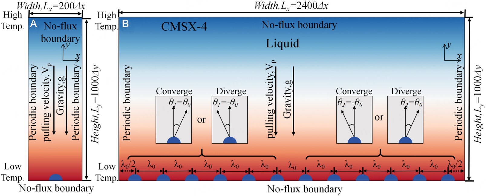
Figure 1. The initial condition and boundary condition of the computational domain: (A) Single crystalline configuration; (B) bi-crystalline configuration.
In this study, the gravitational acceleration g is used as a control parameter to systematically regulate both the intensity and direction of solutal buoyancy-driven natural convection. The gravitational acceleration in the simulation is defined as g = [0, gy], and gy = -g0, -g0/2, -g0/5, g0/5, g0/2, and g0. When all other parameters are fixed, the thermal Rayleigh number RaT = gβTΔcL3/να and the solutal Rayleigh number Rac = gβcΔcL3/νDl, which characterize buoyancy-driven flow induced by temperature and solute concentration gradients, respectively, are linearly proportional to g, thereby representing the strength of the buoyancy-driven forces, where ΔT and Δc denote the temperature difference and solute concentration difference, L is a characteristic length, andα is the thermal diffusivity. Consequently, both positive and negative values of the gravitational acceleration are selected, corresponding to different convection intensities and directions, in order to elucidate the underlying mechanisms by which natural convection influences solute transport, local undercooling, and dendritic tip stability.
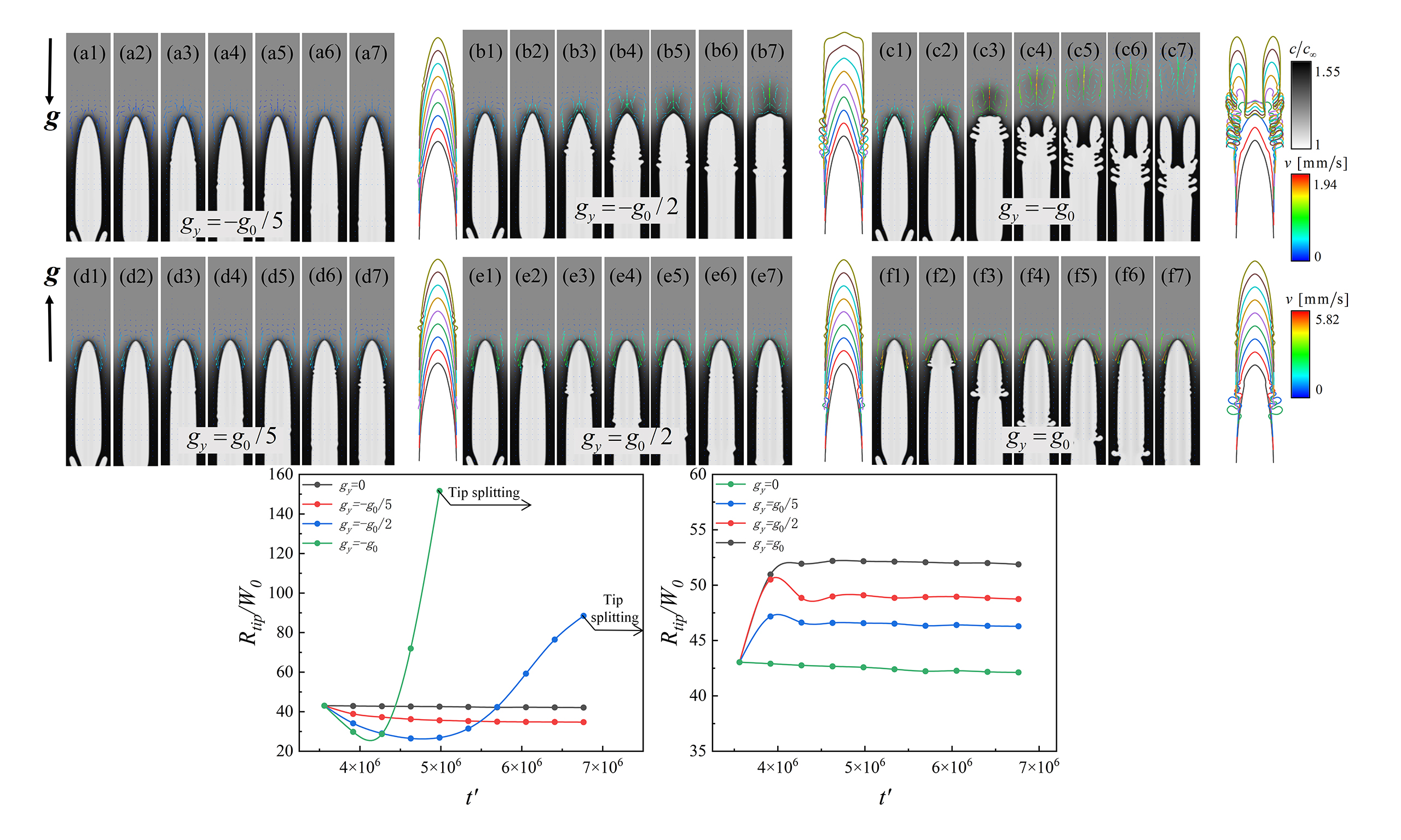
Firstly, we focus on the effect of natural convection on the dendritic tip instability in the single crystalline configuration. In this study, the dendrite with θ1 = 0° grows from the initial seed in the stationary state until a steady dendritic morphology forms (t′ = 3.56 × 10⁶); then, the natural convection was introduced. Note that this numerical processing differs from practical directional solidification, where buoyancy-driven flow develops continuously from the onset of solidification. However, this strategy enables a clear understanding of the instability mechanism of the dendritic tip under natural convection during directional solidification. Figure 2 shows the snapshots of a single dendrite in the downward buoyancy ((A) gy = -g0/5, (B) gy = -g0/2 and (C) gy = -g0) and the upward buoyancy ((D) gy = g0/5, (E) gy = g0/2 and (F) gy = g0) after the natural convection is introduced, where the grayscale indicates the solutal concentration field, and the flow velocity is marked by the colored arrows. Meanwhile, Figure 3 shows the evolution of the solute concentration profiles extracted along the dendrite symmetry axis for the simulation cases presented in Figure 2. Obviously, the strength of natural convection increases with the magnitude of the imposed gravitational acceleration gy. Because the thermal gradient used in our simulations is relatively small (0.005 K/μm), natural convection is mainly caused by the uneven distribution of solute. The solute expansion coefficient βc = 2.986 × 10⁻² wt.%-1 implies that solute atoms are lighter, and hence the rejected solute during dendritic growth will move in the opposite direction of gravity.
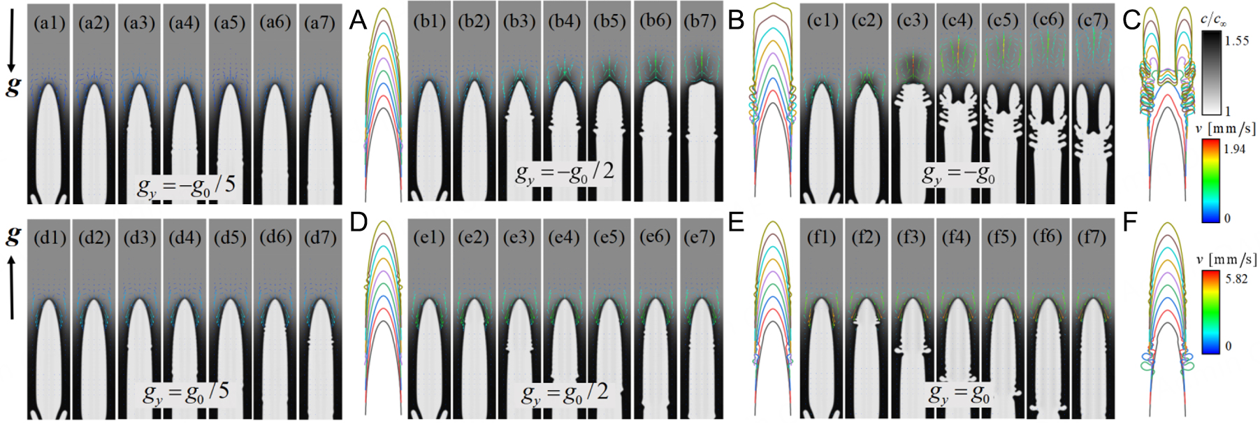
Figure 2. Snapshots of a single dendrite in the downward buoyancy ((A) gy = -g0/5, (B) gy = -g0/2 and (C) gy = -g0) and the upward buoyancy ((D) gy = g0/5, (E) gy = g0/2 and (F) gy = g0) at t′ = 3.92 × 10⁶ to 6.67 × 10⁶, where the grayscale indicates the solutal concentration field, the flow velocity is marked by the colored arrows.
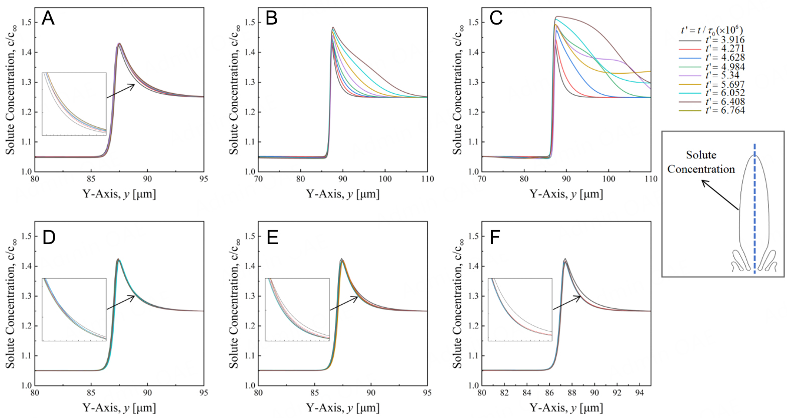
Figure 3. Evolution of the solute distribution along the crystal symmetry axis: (A) gy = -g0/5, (B) gy = -g0/2 and (C) gy = -g0, (D) gy = g0/5, (E) gy = g0/2 and (F) gy = g0.
As shown in Figure 2A-C, for gy < 0, i.e., the gravitational acceleration along y-, the presence of the natural convection transports the solute atoms from the dendritic root towards the dendritic tip. The enrichment of the solute concentration near the dendritic tip lowers the local undercooling and hinders the growth of the dendritic tip. For gy = -g0/5 (see Figure 2A), the effect of natural convection on the dendritic shape is not significant as the convection intensity is relatively weak. As shown in Figure 3A, although the maximum of the solute concentration increases and the solute boundary layer thickens in front of the dendritic tip with the time, the increase is not significant. However, the convection intensity increases with the increase of gy. For gy = -g0/2 (see Figure 2B), more solute atoms are transported from the root towards the dendritic tip. As shown in Figure 3B, the maximum of the solute concentration in front of the dendritic tip significantly increases with the time. Therefore, the enrichment of the solute concentration can significantly slow down the growth of the dendritic tip according to the corresponding equivalent liquidus slope and solute partition coefficient of the equivalent binary alloy. When gy = -g0 (see Figure 2C), the enrichment of the solute concentration can result in the occurrence of dendritic tip splitting. Moreover, as solute-rich liquid flows up, the so-called “plume” forms in front of the dendritic tip, as shown in Figure 3C.
As for gy > 0, as shown in Figure 2D, the presence of natural convection can transport rejected solute atoms from the dendritic tip region towards the dendritic root, resulting in the enrichment of the solute concentration in the interdendritic region. As shown in Figure 3A-C, the solute concentration has an extremum at the dendritic tip, and all the solute concentration versus distance curves overlap after the natural convection is introduced for the cases of gy. This means that natural convection has negligible influence on the solute distribution along the crystal symmetry axis for gy > 0, and the morphology of dendritic tips remains almost unchanged with time although the sidebranches develop just after the convection is introduced.
In order to investigate the influence of natural convection on the dendritic tip instability, the evolution of the dendritic tip radius with time is analyzed after the natural convection is introduced. In this study, the dendritic tip radius is calculated by fitting the contour of ϕi = 0 to a fourth-order interpolation function
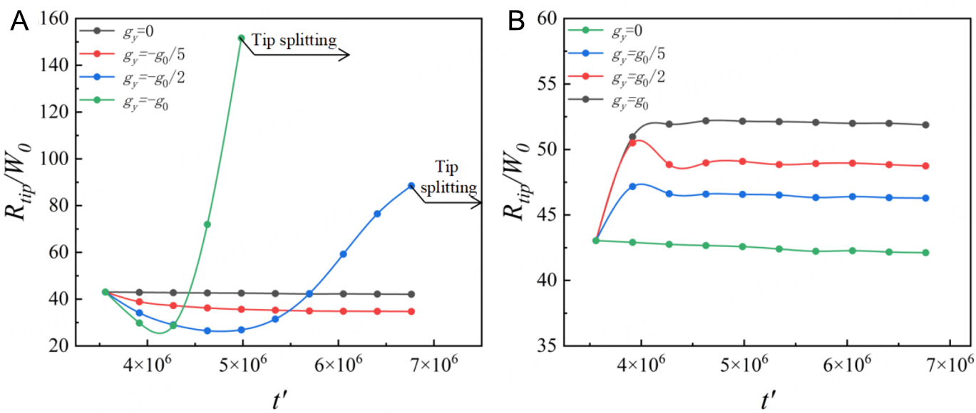
Figure 4. Evolution of the dendritic tip radius over the time: (A) for gy < 0 and (B) for gy > 0.
Then, let us turn to the competitive growth of bi-crystalline grains regarding the evolution of the converging grain boundary under natural convection. Similar to the single configuration, the dendrites grow from the initial seeds in the static state until t′ = 3.56 × 10⁶, and then the natural convection was introduced. Figure 5 shows the snapshots of the bi-crystalline grains with converging grain boundary (θ1, θ2) = (-15°, 15°) in the downward buoyancy ((A) gy = -g0/5, (B) gy = -g0/2 and (C) gy = -g0) and the upward buoyancy ((D) gy = g0/5, (E) gy = g0/2 and (F) gy = g0) after the natural convection was introduced. The primary spacing of the dendritic arrays is history-dependent; i.e., it is determined by the spacing of the initial solid seeds. It can be seen clearly that the natural convection has negligible effect on the dendritic shape and the positions of the dendritic tips in the downward buoyancy except for the obvious sidebranches near the left and right boundaries for lower convection intensity (gy = -g0/5). With the increase of the convection intensity (gy = -g0/2 and gy = -g0), solute-rich liquid flows up and plumes form in front of the dendritic arrays, resulting in the instability of the dendritic tips and the occurrence of the continuous tip splitting. In upward buoyancy, regardless of gravity strength, the morphology of dendrites and the position of the grain boundary remain barely affected by natural convection.
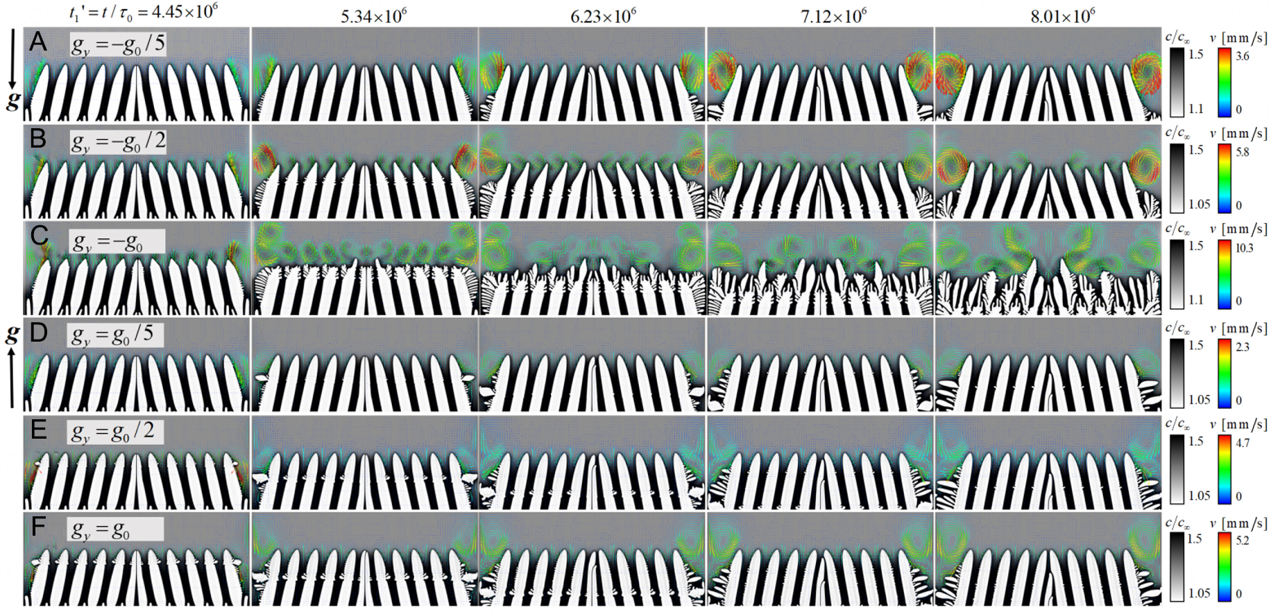
Figure 5. Snapshots of the bi-crystalline grains with the converging grain boundary (θ1, θ2) = (-15°, 15°) in the downward buoyancy
Figure 6 shows the snapshots of the bi-crystalline grains with diverging grain boundary (θ1, θ2) = (-15°, 15°) in the downward buoyancy ((A) gy = -g0/5, (B) gy = -g0/2 and (C) gy = -g0) and the upward buoyancy
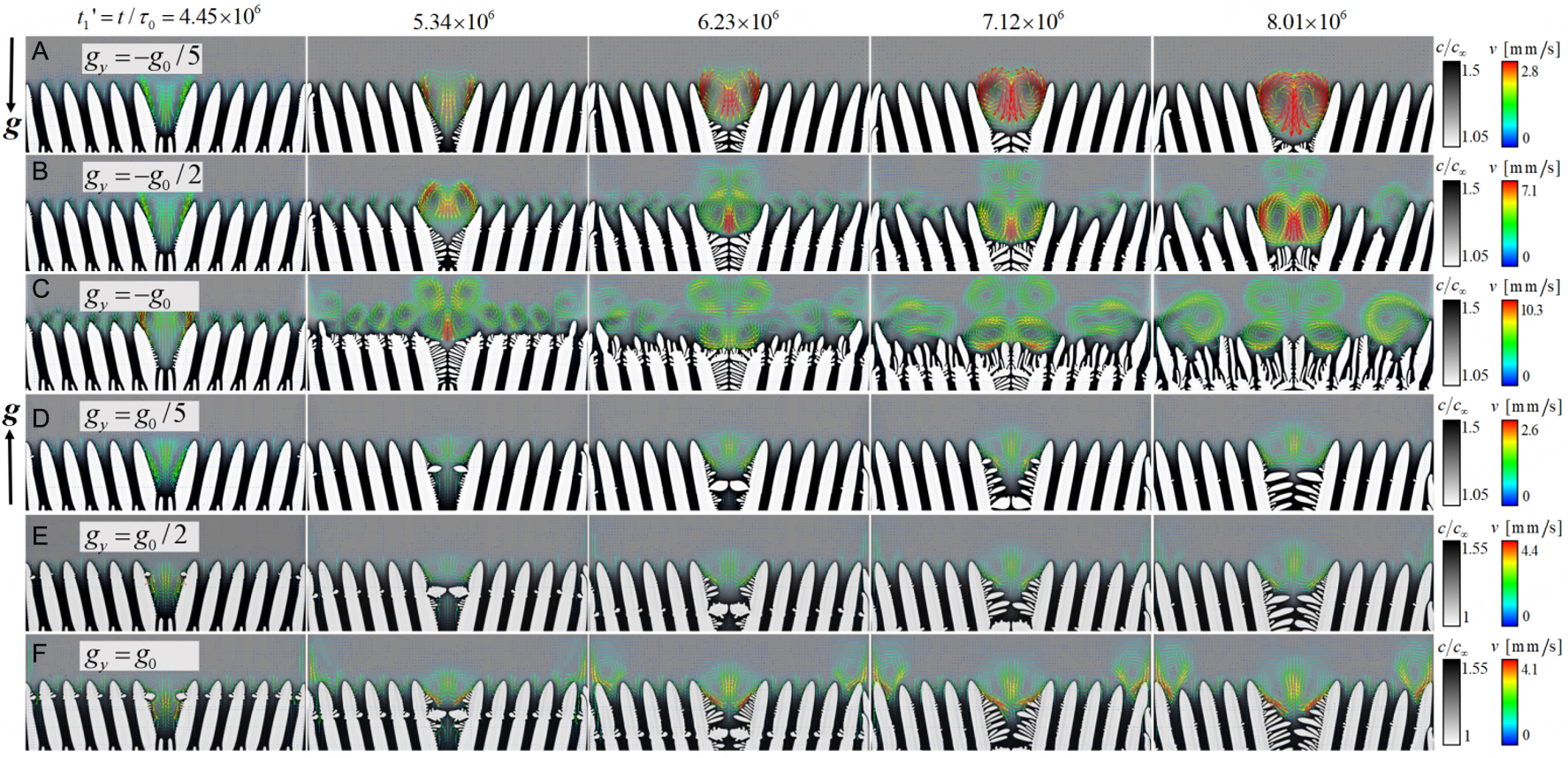
Figure 6. Snapshots of the bi-crystalline grains with diverging grain boundary (θ1, θ2) = (-15°, 15°) in the downward buoyancy
Then, the natural convection is introduced at the beginning of solidification (t′ = 0). The converging and diverging grain boundaries of the bi-crystalline grains are considered. Figure 7 shows the snapshots of the bi-crystalline grains with the converging grain boundary (θ1, θ2) = (-15°, 15°) in the downward buoyancy
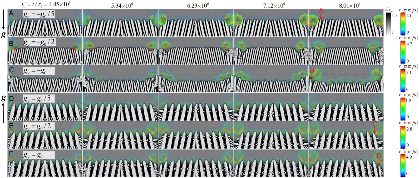
Figure 7. Snapshots of the bi-crystalline grains with the converging grain boundary (θ1, θ2) = (-15°, 15°) in the downward buoyancy
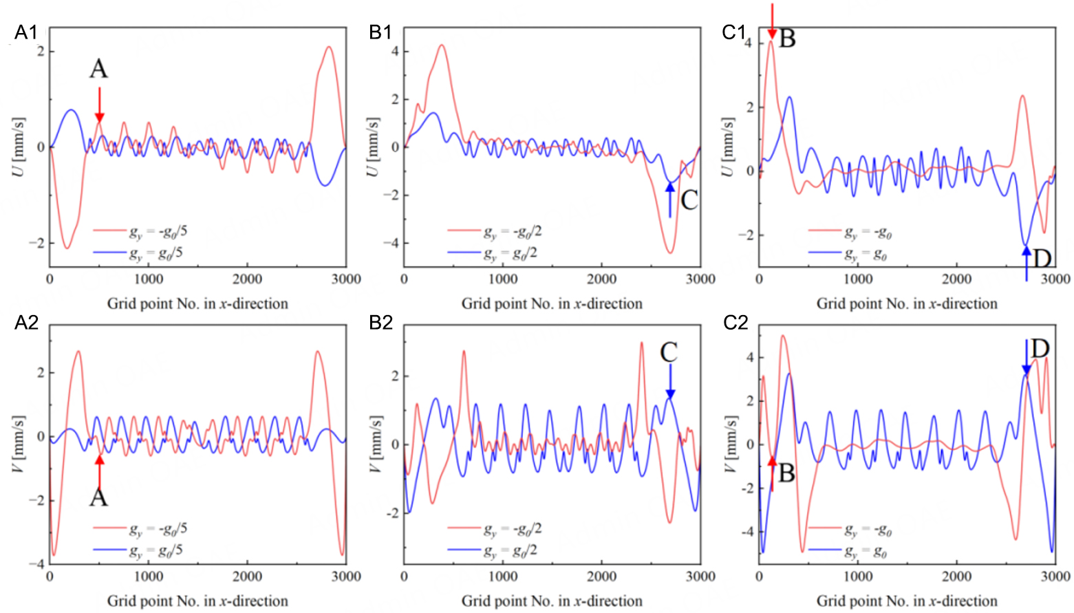
The diverging case is presented in Figure 9. In the case of the downward buoyancy, two elliptical vortex rings form in the liquid zone between the two grains. These large-scale vortices dominate the solute redistribution within the liquid zone. They continuously flush the interdendritic solute from the grain boundary region and carry it towards the dendrite tips on the flanks, thereby creating strong lateral solute gradients. With the increase of the convection intensity, the liquid zone becomes shortened. When gy = -g0, the liquid zone between grains almost disappears, and the solidification front at the grain boundary lags behind other positions. In the case of the upward buoyancy, the liquid zone between the two grains remains almost unchanged, and the increase of the convection intensity promotes the coarsening of secondary sidebranches. Figure 10 shows the flow distribution along the red dashed line in Figure 9, with the velocity component U in the x-direction and the velocity component V in the y-direction. In Figure 9, the arrows with capital letters indicate the positions of the dendrite tips. In front of dendrites E and H, very fast upward and outward flows occur. These flows transport the solute-rich liquid toward the tips of dendrites E and H, enriching the solute boundary layer and stabilizing it against the development of new sidearms, while simultaneously retarding the primary tip advancement, which results in the solute accumulation. Thus, the tip positions of dendrites E and H are lower than those of the other dendrites. In contrast, in front of dendrites F and G, very fast downward and inward flows occur. These flows remove the solute around the tips of dendrites F and G, effectively thinning the solute boundary layer, increasing the local undercooling, and creating conditions favorable for the initiation and sustained growth of sidearms that allow them to grow preferentially. The asymmetric flow pattern thus establishes a competitive growth environment where solute redistribution via convection directly dictates which dendrite arms are favored or suppressed, leading to the observed sidearm development and tip instability.
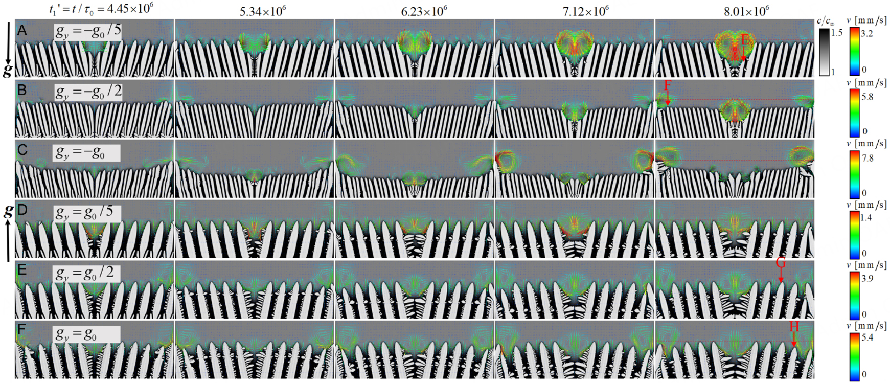
Figure 9. Snapshots of the bi-crystalline grains with diverging grain boundary (θ1, θ2) = (-15°, 15°) in the downward buoyancy
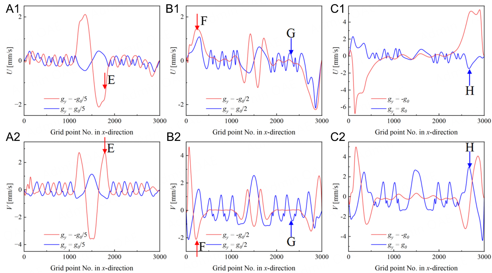
These flow characteristics revealed by the velocity distributions in Figures 8 and 10 provide a foundation for a more general mechanistic understanding of how grain-boundary geometry modulates convection-driven solute transport and dendritic growth behavior. For converging grain boundaries, the narrowing liquid channel enhances the interaction between adjacent solute boundary layers and promotes the formation of coherent upward plumes under downward buoyancy. This geometric confinement amplifies solute accumulation and flow instability in front of the dendritic array, making converging boundaries particularly sensitive to convection-induced tip destabilization. In contrast, diverging grain boundaries provide an expanded liquid region that favors the formation of closed recirculating vortices rather than vertically extended plumes. These vortical flows redistribute solute laterally along the grain boundary, promoting sidebranch development while suppressing the sustained solute accumulation required for primary arm formation. Overall, the present results demonstrate that the influence of natural convection on dendritic growth is governed not only by its intensity and direction, but also by the geometrical characteristics of the grain boundary region. Convection-driven solute redistribution near dendrite tips and grain boundaries, together with the associated changes in local undercooling, provides a consistent mechanistic basis for understanding the observed variations in tip stability, sidebranching, and grain-boundary evolution under different gravitational conditions.
CONCLUSIONS
In this paper, the coupled PF-LBM method is employed to reliably simulate complex dendritic growth phenomena including solutal plumes, vortex structures, and tip splitting under natural convection during directional solidification of alloys. We implement the coupled equations by using in-house code written in CUDA. Compared with previous studies, this work elucidates the physical mechanisms by which natural convection regulates dendrite tip stability. It is found that in the single crystalline case the impact of natural convection on the dendritic tip stability depends strongly on gravitational direction and intensity. Downward buoyancy promotes solute accumulation at tips, enhancing tip instability, while upward buoyancy moves solute away from tips to interdendritic regions, thereby stabilizing the dendritic tips. In the bi-crystalline case, the solute transport and dendritic growth depend strongly on the grain boundary type (converging or diverging). Converging boundaries are sensitive to the downward buoyancy-induced instability, while diverging boundaries form vortex-driven solute flow that promotes sidebranching and primary arms in the downward buoyancy or inhibits primary arms in upward buoyancy. The proposed PF-LBM framework provides a robust and efficient platform for quantitatively exploring the interplay between fluid dynamics and microstructural evolution, offering valuable theoretical insights for optimizing solidification parameters and minimizing defect formation in industrial casting processes.
DECLARATIONS
Authors’ contributions
Research concept and design: Xie, Y.; Jing, H.; Zheng, Y.; Zhai, W.; Xing, H.
Data acquisition and analysis: Xing, H.; Xie, Y.; Jing, H.
Manuscript preparation: Xing, H.; Xie, Y.
Supervision: Xing, H.; Zheng, Y.; Zhai, W.
Availability of data and materials
Data supporting the findings of this study are available from the corresponding author upon reasonable request.
AI and AI-assisted tools statement
Not applicable.
Financial support and sponsorship
This work is supported by the National Key Research and Development Program of China (No. 2021YFB3502600) and Shenzhen Science and Technology Innovation Program (No. JCYJ20220530161813029).
Conflicts of interest
All authors declared that there are no conflicts of interest.
Ethical approval and consent to participate
Not applicable.
Consent for publication
Not applicable.
Copyright
© The Author(s) 2026.
REFERENCES
1. Behera, A.; Sahoo, A. K.; Mahapatra, S. S. Electrical discharge machining of Ni-based superalloy and its applications in aero turbine parts: a comprehensive review. Adv. Mater. Proc. Technol. 2024, 11, 1085-121.
2. Al-nafeay, R. H.; Al-Roubaiy, A. O.; Omidvar, H. Overview of joining and repairing techniques of Ni-based superalloy for industrial gas turbine applications. IOP. Conf. Ser. Mater. Sci. Eng. 2021, 1094, 012141.
3. Yang, L.; Ren, N.; Li, J.; et al. Thermal-solutal convection-induced low-angle grain boundaries in single-crystal nickel-based superalloy solidification. J. Mater. Sci. Technol. 2025, 208, 214-29.
4. Chen, Y.; Yao, Z.; Dong, J.; et al. Microstructural deterioration mechanism of directionally solidified Ni-based superalloy used in first-stage industrial gas turbine blades after ultra long-term service. Mater. Charact. 2024, 213, 114000.
5. Yan, X.; Xu, Q.; Tian, G.; Liu, Q.; Hou, J.; Liu, B. Multi-scale modeling of liquid-metal cooling directional solidification and solidification behavior of nickel-based superalloy casting. J. Mater. Sci. Technol. 2021, 67, 36-49.
6. Guo, C.; Zha, H.; Wang, J.; et al. Coupled PF and LB simulation study of morphology evolution in columnar dendrite growth induced by natural convection. Results. Phys. 2025, 77, 108452.
7. Ren, N.; Li, J.; Panwisawas, C.; Xia, M.; Dong, H.; Li, J. Insight into the sensitivities of freckles in the directional solidification of single-crystal turbine blades. J. Manuf. Proc. 2022, 77, 219-28.
8. Zhang, H.; Zhao, Y.; Xiong, W.; et al. Modelling freckles and spurious grain formation in directionally solidified superalloy castings. Commun. Mater. 2024, 5, 232.
9. Yang, L.; Ren, N.; Xia, M.; Li, J.; Li, J. Multiphysics modeling of dendritic thermomechanical deformation during the directional solidification of nickel-based single-crystal superalloys. Int. J. Miner. Metall. Mater. 2025, 32, 2510-22.
10. Liu, Y.; Shang, Y.; Wang, F.; et al. A novel model of the cross-section variation effect induced by contraction convection on freckle defects in directional solidification. J. Mater. Res. Technol. 2025, 35, 570-80.
11. Reinhart, G.; Browne, D. J.; Kargl, F.; et al. In-situ X-ray monitoring of solidification and related processes of metal alloys. NPJ. Microgravity. 2023, 9, 70.
12. Zhang, Z.; Wang, C.; Koe, B.; Schlepütz, C. M.; Irvine, S.; Mi, J. Synchrotron X-ray imaging and ultrafast tomography in situ study of the fragmentation and growth dynamics of dendritic microstructures in solidification under ultrasound. Acta. Mater. 2021, 209, 116796.
13. Nagira, T.; Kitano, H.; Kimura, T.; et al. In-situ observation of solidification behaviors of Fe-Mn-Cr-Ni-Si alloy during TIG melt-run welding using synchrotron radiation X-ray. Mater. Charact. 2024, 214, 114093.
14. Wu, F.; Mullen, J.; Deng, Y.; et al. Probing dendrite growth under microgravity via machine learning-aided multi-scale characterisation. Acta. Mater. 2026, 302, 121659.
15. Shevchenko, N.; Budenkova, O.; Chichignoud, G.; Eckert, S. Formation of varying dendritic morphologies in a directionally solidifying Ga-In-Bi alloy. Acta. Mater. 2025, 288, 120818.
16. Neumann-heyme, H.; Shevchenko, N.; Grenzer, J.; Eckert, K.; Beckermann, C.; Eckert, S. In-situ measurements of dendrite tip shape selection in a metallic alloy. Phys. Rev. Mater. 2022, 6, 063401.
17. Ruvalcaba, D.; Mathiesen, R.; Eskin, D.; Arnberg, L.; Katgerman, L. In situ observations of dendritic fragmentation due to local solute-enrichment during directional solidification of an aluminum alloy. Acta. Mater. 2007, 55, 4287-92.
18. Reinhart, G.; Grange, D.; Abou-Khalil, L.; et al. Impact of solute flow during directional solidification of a Ni-based alloy: in-situ and real-time X-radiography. Acta. Mater. 2020, 194, 68-79.
19. Xie, L.; Sun, H.; Wen, Y.; Hua, L.; Zhang, L. Electromagnetic treatment enhancing performance of metal materials: a review. Prog. Mater. Sci. 2025, 153, 101488.
20. Hu, Z.; Huang, C.; Xie, L.; Hua, L.; Yuan, Y.; Zhang, L. Machine learning assisted quality control in metal additive manufacturing: a review. Adv. Powder. Mater. 2025, 4, 100342.
21. Wang, B.; Tong, X.; Yu, P.; Tian, J.; Ouyang, H. An immersed boundary finite-volume method based on the wall shear stress model for incompressible Navier-Stokes equations. Ocean. Eng. 2026, 343, 123182.
22. Dobravec, T.; Mavrič, B.; Zahoor, R.; Šarler, B. A coupled domain-boundary type meshless method for phase-field modelling of dendritic solidification with the fluid flow. Int. J. Numer. Methods. Heat. Fluid. Flow. 2023, 33, 2963-81.
23. Xia, Q.; Lai, S.; Kim, J.; Li, Y. Phase field modeling of melting and solidification dynamics in metallic powders during the bed fusion process. Commun. Nonlinear. Sci. Numer. Simul. 2025, 146, 108762.
24. Shankar, B.; Shivakumara, I. Stability of natural convection in a vertical layer of Navier-Stokes-Voigt fluid. Int. Commun. Heat. Mass. Transfer. 2023, 144, 106783.
25. Zhang, X.; Kang, J.; Guo, Z.; Xiong, S.; Han, Q. Development of a Para-AMR algorithm for simulating dendrite growth under convection using a phase-field-lattice Boltzmann method. Comput. Phys. Commun. 2018, 223, 18-27.
26. Miller, W. The lattice Boltzmann method: a new tool for numerical simulation of the interaction of growth kinetics and melt flow. J. Cryst. Growth. 2001, 230, 263-9.
27. Miller, W.; Succi, S.; Mansutti, D. Lattice Boltzmann model for anisotropic liquid-solid phase transition. Phys. Rev. Lett. 2001, 86, 3578-81.
28. Rojas, R.; Takaki, T.; Ohno, M. A phase-field-lattice Boltzmann method for modeling motion and growth of a dendrite for binary alloy solidification in the presence of melt convection. J. Comput. Phys. 2015, 298, 29-40.
29. Yang, Q.; Zhang, A.; Jiang, B.; et al. Numerical investigation of eutectic growth dynamics under convection by 3D phase-field method. Comput. Math. Appl. 2022, 114, 83-94.
30. Sun, D.; Pan, S.; Han, Q.; Sun, B. Numerical simulation of dendritic growth in directional solidification of binary alloys using a lattice Boltzmann scheme. Int. J. Heat. Mass. Transfer. 2016, 103, 821-31.
31. Sun, D.; Zhu, M.; Wang, J.; Sun, B. Lattice Boltzmann modeling of bubble formation and dendritic growth in solidification of binary alloys. Int. J. Heat. Mass. Transfer. 2016, 94, 474-87.
32. Zhang, A.; Du, J.; Guo, Z.; Wang, Q.; Xiong, S. Evolution of specific interface area during solidification: a three-dimensional thermosolutal phase-field study. Comput. Phys. Commun. 2021, 267, 108042.
33. Zhang, A.; Meng, S.; Guo, Z.; Du, J.; Wang, Q.; Xiong, S. Dendritic growth under natural and forced convection in Al-Cu alloys: from equiaxed to columnar dendrites and from 2D to 3D phase-field simulations. Metall. Mater. Trans. B. 2019, 50, 1514-26.
34. Qiu, Y.; Wu, M.; Qin, X.; Xiong, S. Phase-field lattice-Boltzmann study on fully coupled thermal-solute-convection dendrite growth of Al-Cu alloy. China. Foundry. 2024, 21, 125-36.
35. Zhang, Y.; Zhou, J.; Yin, Y.; Ji, X.; Shen, X.; Guo, Z. Study on the solutal convection during dendrite growth of superalloy under directional solidification condition. J. Mater. Res. Technol. 2023, 23, 3916-27.
36. Yang, C.; Xu, Q. Y.; Liu, B. C. Phase‐field-lattice Boltzmann simulation of dendrite growth under natural convection in multicomponent superalloy solidification. Rare. Metals. 2019, 39, 147-55.
37. Lee, J.; Ohno, M.; Shibuta, Y.; Takaki, T. Uniquely selected primary dendrite arm spacing during competitive growth of columnar grains in Al-Cu alloy. J. Cryst. Growth. 2021, 558, 126014.
38. Takaki, T.; Sakane, S.; Ohno, M.; Shibuta, Y.; Aoki, T. Large-scale phase-field lattice Boltzmann study on the effects of natural convection on dendrite morphology formed during directional solidification of a binary alloy. Comput. Mater. Sci. 2020, 171, 109209.
39. Takaki, T.; Sakane, S.; Aoki, T. Natural convection on dendrite morphology: a high-performance phase-field Lattice Boltzmann Study. ISIJ. Int. 2023, 63, 83-90.
40. Ma, C.; Zhang, R.; Li, Z.; et al. Solidification shrinkage and shrinkage-induced melt convection and their relation with solute segregation in binary alloys. Comput. Mater. Sci. 2022, 215, 111815.
41. Yang, L.; Dong, Z.; Wang, L.; Provatas, N. Improved multi-order parameter and multi-component model of polycrystalline solidification. J. Mater. Sci. Technol. 2022, 101, 217-25.
42. Ma, D.; Wu, Q.; Bührig-Polaczek, A. Some new observations on freckle formation in directionally solidified superalloy components. Metall. Mater. Trans. B. 2011, 43, 344-53.
43. Ren, N.; Panwisawas, C.; Li, J.; Xia, M.; Dong, H.; Li, J. Solute enrichment induced dendritic fragmentation in directional solidification of nickel-based superalloys. Acta. Mater. 2021, 215, 117043.
44. Felicelli, S. D.; Poirier, D. R.; Heinrich, J. C. Modeling freckle formation in three dimensions during solidification of multicomponent alloys. Metall. Mater. Trans. B. 1998, 29, 847-55.
45. Felicelli, S. D.; Sung, P. K.; Poirier, D. R.; Heinrich, J. C. Transport properties and transport phenomena in casting nickel superalloys. Int. J. Thermophys. 2014, 19, 1657-69.
46. Sun, Q. Y.; Ren, Y.; Liu, D. Numerical investigations of freckles in directionally solidified nickel-based superalloy casting with abrupt contraction in cross section. Results. Phys. 2019, 12, 1547-58.
47. Matache, G.; Stefanescu, D. M.; Puscasu, C.; Alexandrescu, E. Dendritic segregation and arm spacing in directionally solidified CMSX-4 superalloy. Int. J. Cast. Metals. Res. 2016, 29, 303-16.
48. Schneider, M. C.; Gu, J. P.; Beckermann, C.; Boettinger, W. J.; Kattner, U. R. Modeling of micro- and macrosegregation and freckle formation in single-crystal nickel-base superalloy directional solidification. Metall. Mater. Trans. A. 1997, 28, 1517-31.
49. Sung, P. K.; Poirier, D. R.; Felicelli, S. D. Simulating the initiation of a channel during directional solidification of a superalloy. Metall. Mater. Trans. A. 2001, 32, 202-7.
50. Hobbs, R. A.; Tin, S.; Rae, C. M. F. A castability model based on elemental solid-liquid partitioning in advanced nickel-base single-crystal superalloys. Metall. Mater. Trans. A. 2005, 36, 2761-73.
51. Chen, S.; Doolen, G. D. Lattice Boltzmann method for fluid flows. Annu. Rev. Fluid. Mech. 1998, 30, 329-64.
52. Qian, Y. H.; D'humières, D.; Lallemand, P. Lattice BGK models for navier-stokes equation. Europhys. Lett. 1992, 17, 479-84.
53. Beckermann, C.; Diepers, H.; Steinbach, I.; Karma, A.; Tong, X. Modeling melt convection in phase-field simulations of solidification. J. Comput. Phys. 1999, 154, 468-96.
54. Medvedev, D.; Kassner, K. Lattice Boltzmann scheme for crystal growth in external flows. Phys. Rev. E. Stat. Nonlin. Soft. Matter. Phys. 2005, 72, 056703.
Cite This Article
How to Cite
Download Citation
Export Citation File:
Type of Import
Tips on Downloading Citation
Citation Manager File Format
Type of Import
Direct Import: When the Direct Import option is selected (the default state), a dialogue box will give you the option to Save or Open the downloaded citation data. Choosing Open will either launch your citation manager or give you a choice of applications with which to use the metadata. The Save option saves the file locally for later use.
Indirect Import: When the Indirect Import option is selected, the metadata is displayed and may be copied and pasted as needed.
About This Article
Special Topic
Copyright

Data & Comments
Data
0


Comments
Comments must be written in English. Spam, offensive content, impersonation, and private information will not be permitted. If any comment is reported and identified as inappropriate content by OAE staff, the comment will be removed without notice. If you have any queries or need any help, please contact us at [email protected].