

Industrial waste heat utilization for combined hydrogen and electricity generation
 0
0 
Abstract
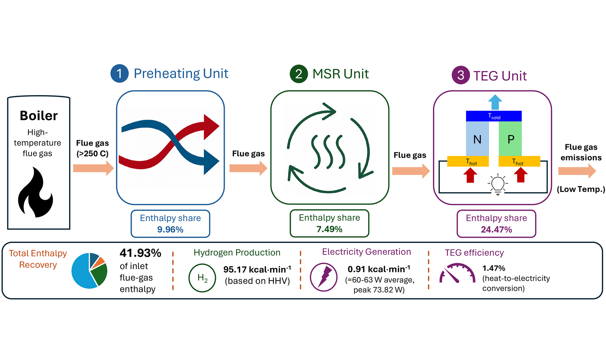
This study presents an integrated triple-unit recovery system (ITURS) for converting the enthalpy of industrial flue-gas into hydrogen and electrical power through temperature-matched heat utilization. The system consists of preheating, methanol steam reforming (MSR), and thermoelectric generation (TEG) units arranged in series. In the preheating section, the methanol solution is vaporized before entering the reformer. The MSR unit, packed with Cu-Zn bimetallic catalysts, receives 7.49% of the inlet enthalpy to maintain the thermal conditions required for the endothermic reforming reaction, resulting in methanol conversions above 90% and hydrogen concentrations close to 70 vol%. The TEG unit utilizes 24.47% of the inlet enthalpy to establish the temperature difference across the thermoelectric modules for power generation. The system produces an average electrical output of 60-63 W, with a peak output of 73.82 W. The TEG exhibited a heat-to-electricity conversion efficiency of 1.47% under practical operating conditions. Overall, the ITURS recovers 41.93% of the available flue-gas enthalpy. Under the tested conditions, the system generates 95.17 kcal·min-1 of hydrogen energy based on higher heating value and 0.91 kcal·min-1 of electrical power. These results demonstrate that the integrated ITURS can effectively co-generate hydrogen and electricity by utilizing industrial waste heat through units integrated in series across sequential recovery stages.
Keywords
INTRODUCTION
Reducing reliance on fossil fuels and developing renewable energy remain key priorities in order to achieve global sustainability. In fact, energy input is necessary for industrial processes[1]. While energy consumption in industrial activities is increasing, a large portion of it is liberated as waste heat, creating a serious energy waste problem. Methods for recovering waste heat can be categorized as direct use and heat conversion. On the one hand, waste heat can be directly used with devices such as radiation/convection recuperators, passive air preheaters, boilers, economizers, and plate heat exchangers[2]. In the industrial sector, using waste heat for preheating purposes has become standard practice. On the other hand, heat conversion systems help utilize waste heat by converting it into various forms of energy that are suitable for a wide range of purposes, such as mechanical work, power generation, and chemical reactions.
Heat can be converted into different forms to power devices such as vapor-compression heat pumps, absorption heat pumps, and absorption heat transformers[3]. A vapor-compression heat pump consumes electricity, while an absorption heat pump and an absorption heat transformer are driven by heat. Secondly, heat-to-power conversion is achieved through widely adopted methods such as the organic Rankine cycle (ORC)[4] and the Kalina cycle[5]. The typical Kalina cycle is more efficient at higher driving temperatures, while the organic Rankine cycle is more suitable for lower driving temperatures[6]. Additional heat-to-power techniques involve thermoelectric generators (TEGs)[7], electrochemical systems[8], thermogalvanic cells[9], and pyroelectric energy conversion[10], all of which have yet to be deployed for large-scale industrial production. Last but not least, heat can enhance the productivity or efficiency of chemical reactions by providing the heat required.
Regardless of whether waste heat is recovered for direct use or conversion, flue gas waste heat above 650 °C has been preferred by industries due to its high energy content. High-temperature waste heat has been used for power generation with relatively mature technologies such as steam turbines. Middle-temperature waste heat, with temperatures ranging from 250 to 650 °C, has a mixed track record of industrial applicability. In contrast, technologies for recovering low-temperature waste heat have remained underdeveloped. The industrial use of recycled low-temperature waste heat has been limited to fuel preheating, space heating, and foodstuff drying[11]. Nevertheless, low-temperature waste heat accounts for a significant share of total waste heat worldwide. A survey conducted by the U.S. Department of Energy on such energy-intensive industries as glass, cement, iron/steel, aluminum, metal casting, and ethylene industries shows they consume as much as 8.86 EJ of energy annually, which accounts for 9% of the total energy consumption in the United States (~92 EJ). Every year, 1.56 EJ of waste heat dissipates into the environment, of which approximately 60% is carried by emissions below 250 °C[12].
Given the substantial availability of low-temperature waste heat, much of which dissipates at temperatures below 250 °C, there is growing interest in redirecting this otherwise wasted energy toward thermochemical processes, particularly for hydrogen production. Hydrogen can be produced through four main approaches: (1) thermochemical methods, such as natural gas reforming and the gasification of coal and biomass[13], (2) electrochemical methods[14], (3) photocatalysis[15], and (4) biological methods[16]. Among these, thermochemical methods have the greatest potential for commercialization or large-scale production because the energy input required for these processes is readily available from industrial waste heat. The MSR process, for instance, requires a reaction temperature between 200 and
Another effective way of making use of low-temperature waste heat is generating electricity with a thermoelectric generator (TEG), which stands out among practical waste heat recovery methods as highly durable and environmentally friendly[19,20]. The TEG operates according to the Seebeck effect, where an electric current is induced by a temperature difference between the ends of a pair of parallel metal bars made of materials with different electric potentials[21]. To maximize TEG power generation, various combinations of materials, such as Bi-Te, Si-Ge, Pb-Te, skutterudite, etc., have been employed and found to be more efficient in some temperature ranges than others[22]. The Bi-Te alloy, for instance, works the best between 100 and 300 °C[23], generating the greatest amount of electricity with the highest Seebeck coefficient (S), and, hence, thermoelectric figure-of-merit (
Given the unsatisfactory performance for low-temperature waste heat recovery, it is desirable to improve overall waste heat recovery efficiency. One way to achieve this goal is to combine multiple waste-heat recovery units in series to fully exploit both high- and low-temperature waste heat. Candidates for constituting the series units include fuel preheating, methanol steam reforming (MSR), and thermoelectric generation systems. According to the European Union (EU) statistics, low-temperature waste heat below 250 °C accounts for 75% of the total industrial waste heat[25]. Therefore, the development of low-grade waste-heat recovery is receiving worldwide attention. Low-temperature waste heat can be used to transform liquid fuel into a gaseous form, converting heat energy into chemical energy. Hydrogen can be extracted from a methanol solution via MSR, demonstrating a form of heat-to-thermochemical conversion[26]. Accordingly, an MSR unit and a TEG unit are installed to work alongside a preheating unit, forming an industrial-scale system. The preheating unit is designed to heat the methanol solution utilizing high-temperature waste heat. Medium-temperature waste heat is then used to drive reactions in the MSR unit, producing hydrogen. Lastly, two sets of TEGs are installed along the exhaust to recover low- to medium-temperature waste heat from the MSR, utilizing the temperature gradient between the exhaust interior and the surrounding environment. This study is motivated by the need to effectively utilize low- to medium- grade industrial waste heat through a temperature-matched integration strategy. By quantifying heat recovery efficiencies across preheating, MSR, and thermoelectric generation units, the proposed system shows how sequential integration of technologies can maximize overall energy utilization and support scalable industrial implementation.
EXPERIMENTAL
Waste heat production unit
The schematic of the entire waste heat recovery system is illustrated in Figure 1. An automated temperature control unit, incorporating a combustion controller and a thermocouple reader, was installed to maintain the system temperature throughout the process. The volume and flow rate of gases were also controlled with automated devices. A boiler fueled by liquefied petroleum gas (LPG), a hollow steel cylinder with a diameter of 80 cm and a height of 180 cm, was used to simulate the source of industrial waste heat (fiery center at 1,350 °C). A burning control valve was installed at the inlet of the gaseous fuel at the top of the boiler. After natural gas combustion, the hot flue gas flowed through a side pipe to the preheating unit at the bottom of the series of waste heat recovery units. The design of the three heat recovery units is explained in detail in the following subsections.
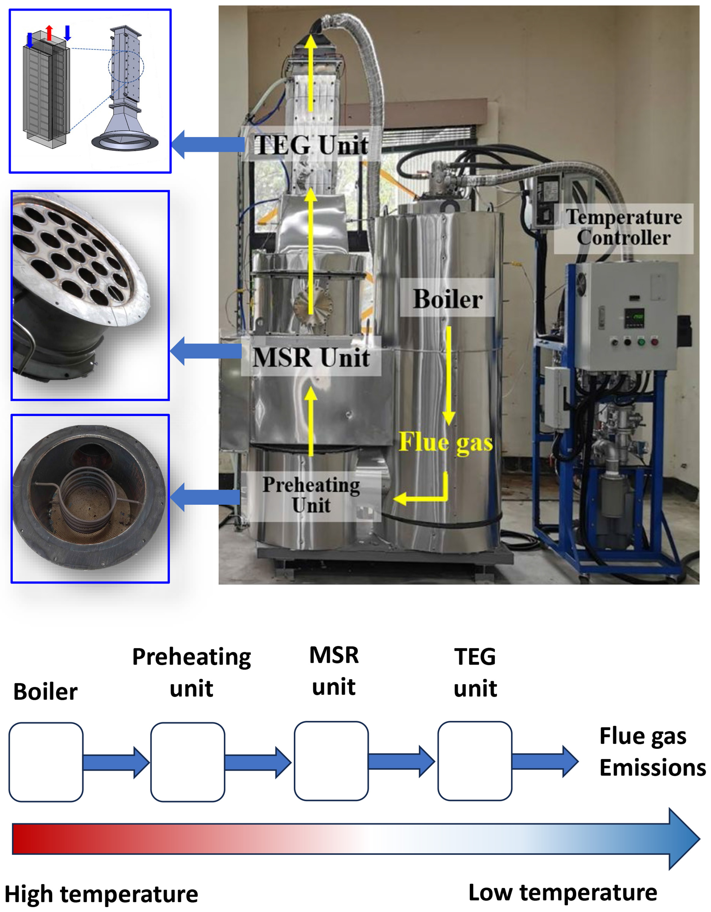
Figure 1. Schematic diagram of the integrated triple-unit system. (Photograph taken by the authors). TEG: thermoelectric generation; MSR: methanol steam reforming.
Preheating unit
The preheating unit was a hollow cylinder with a diameter of 50 cm and a height of 30 cm. It was connected to a boiler on the side and an MSR unit on top. The waste heat generated by the boiler was circulated in the coils within the preheating unit before being sent to the MSR unit. An elastic copper tube, 2 m long and with an inside diameter of 5 mm, was used to bring the methanol solution (ambient temperature) into the preheating unit, where the high-temperature air surrounding the tube vaporized the liquid, and then sent it up into the MSR unit. To monitor temperatures, a thermocouple was installed at the center of the preheating unit, and another at the center of the duct connecting the unit to the boiler.
Methanol steam reforming unit
As an endothermic reaction [Equation 1], MSR can use the waste heat from the boiler to produce hydrogen. Accordingly, the MSR unit, consisting of a number of stainless steel tubes, two thermocouples, a pump (Nikuni pump), and a gas analyzer (MRU Vario Plus Industrial), was built in the form of a shell-and-tube heat exchanger [Figure 2] to convert methanol solution into hydrogen through recovered heat. A cylindrical shell with a 0.5 m diameter was designed to contain up to 50 kg of Cu-Zn particles to catalyze an MSR reaction on an industrial scale. A methanol solution with a steam-to-carbon (S/C) ratio of 2.5 was pumped into the reaction space at a volume of 10~100 mL∙min-1 to react with the aid of the Cu-Zn catalyst. Nineteen (19) stainless steel tubes were vertically installed in the shell to allow flue gas from the boiler to pass through the reaction space, thereby triggering the MSR reaction via heat transfer. To remove the gaseous products of the MSR, pressurized N2 was directed horizontally through the reaction space from one side to the other at a flow rate of 3,000 mL·min-1. A flow meter was installed at the outlet to measure the flow rate of the outgoing gas. Its composition (H2, CO, CO2, and CH4) was then analyzed using a gas analyzer (MGAprime H2, MRU Messgeräte für Rauchgase und Umweltschutz GmbH, Germany). Two K-type thermocouples were inserted into the catalyst bed, one at the middle section and one near the bottom of the reaction zone, to monitor the temperature distribution. The reactor temperature was controlled at 200 or 250 °C, with the thermocouple at the center of the catalyst bed serving as the control point. In the constructed packed bed, axial and radial temperature gradients are inevitable; the mid-bed location was therefore selected as a reference to limit variation in the effective reaction zone and maintain stable operating conditions.
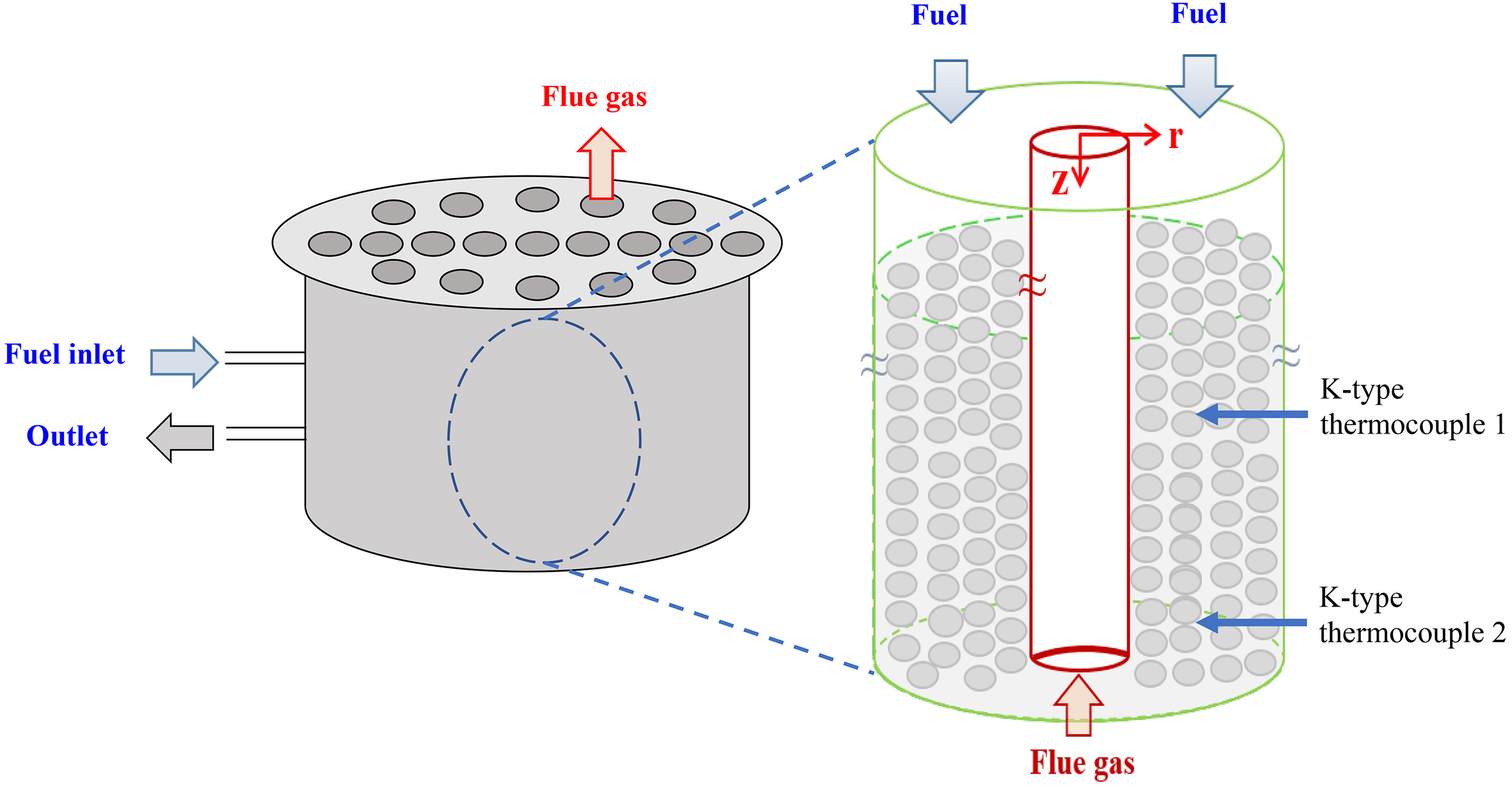
Figure 2. Internal configuration and catalyst packing of the shell-and-tube MSR reactor. MSR: Methanol steam reforming.
Thermoelectric generation unit
The third heat recovery unit consisted of thermoelectric generators (TEGs), which are considered durable and environmentally friendly devices[27]. It is especially suitable for recovering low- and medium-temperature waste heat because the TEG’s ability to generate electricity is based on the temperature difference across the generators rather than a high-temperature environment. The TEG unit comprised a square array of thermoelectric modules (TEMs) made of low-resistance metals, so that electrons in the TEMs could more easily be induced to flow from an area with relatively high temperature to an area with relatively low temperature, thereby generating electric current. Figure 3 depicts the apparatus employed in the present study, in which two TEGs (TG1-1018) were attached to the exterior of a rectangular exhaust (691 mm × 236 mm ×
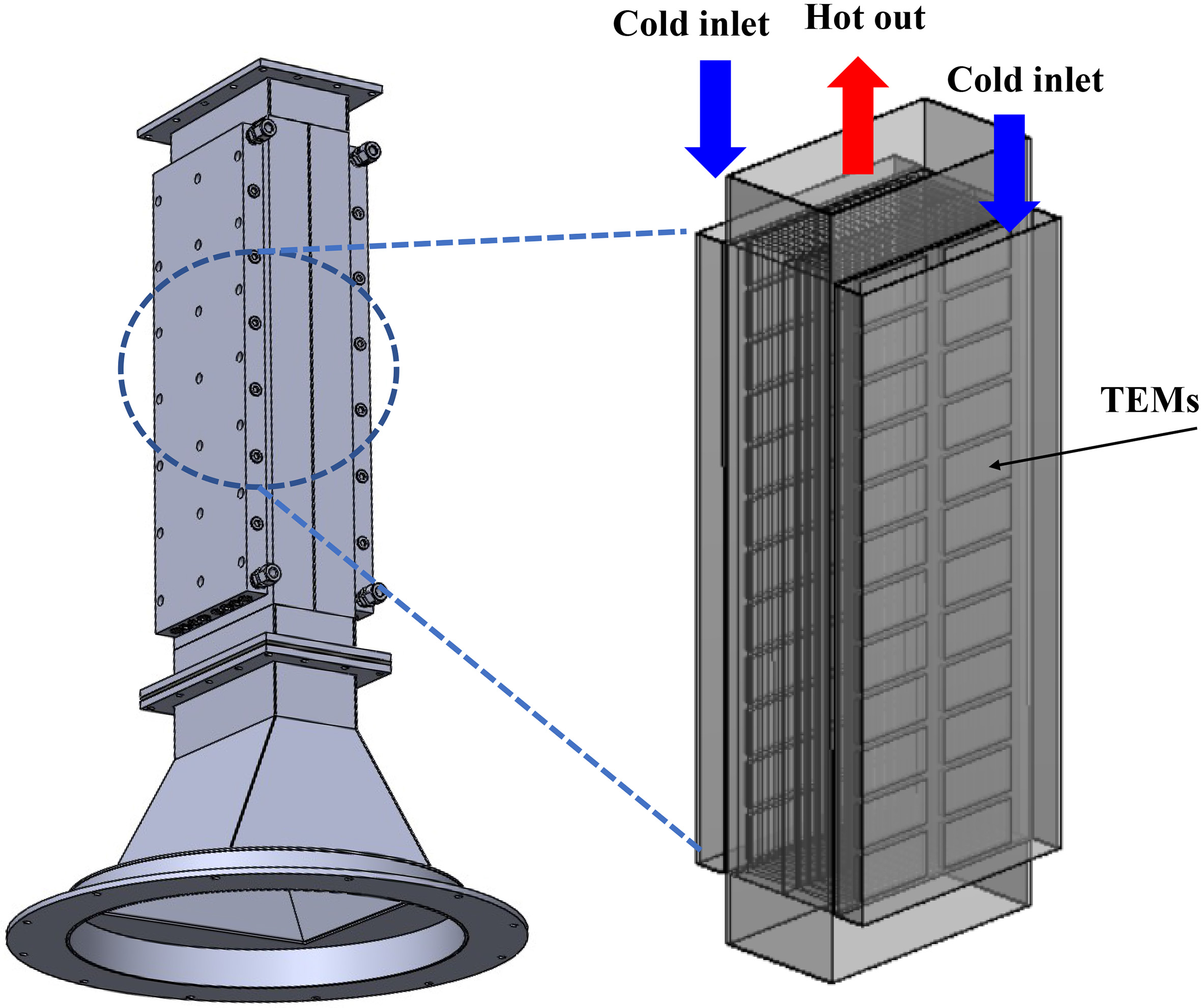
Figure 3. Illustration of the thermoelectric generator assembly, cooling tanks, and internal fins. TEMs: Thermoelectric modules.
Experimental parameters
To evaluate the integrated ITURS under suitable operating conditions, two operating cases were selected according to the thermal stability of the Cu-Zn catalyst. Cu-Zn catalysts used for MSR generally exhibit stable activity between 200 and 300 °C, whereas prolonged exposure to temperatures above 350 °C may deactivate the catalysts and reduce hydrogen production[28,29]. In the reactor, temperature gradients developed along the catalyst bed during operation, particularly near the lower section exposed to direct flue-gas heating. To avoid local overheating, the reactor temperature was controlled using the thermocouple positioned at the center of the catalyst bed (thermocouple 1), while the lower thermocouple (thermocouple 2) was used to monitor temperature variation near the bottom region [Figure 2]. In Case 1, the MSR temperature was maintained at 200 °C, and in Case 2, it was controlled at 250 °C to explore the effects of temperature on the efficacy of waste heat recovery. Before use, the catalyst was activated by hydrogen reduction at 350 °C for 24 h to promote high methanol conversion and hydrogen productivity. Temperature control was achieved by controlling the LPG flow rate into the boiler to support combustion, using an automated control unit. While temperature data were obtained with thermocouples installed in a host of different locations across the system, the automated temperature controller was programmed to act based on readings from the one installed in the middle of the shell, which was filled up with 50 kg of Cu-Zn catalysts [Figure 2]. In addition, cooling water at a flow rate of 0.2 kg∙s-1 maintained at 5-
RESULTS AND DISCUSSION
LPG consumption rate and system temperatures
Figure 4 shows the hourly LPG consumption in the two experimental runs used to simulate industrial waste heat. Conducted with the catalyst bed heated to 200 °C, the first run (Case 1) consumes 4.4 kg∙h-1. In the second run (Case 2) with the catalyst bed heated to 250 °C and all other parameters held constant, the LPG consumption rate increases to 5.0 kg∙h-1. Accordingly, when the catalyst bed temperature is increased by 50 °C, from 200 to 250 °C, the system requires additional heat input, leading to an approximately 13.6% increase in the LPG consumption rate under stable operating conditions.
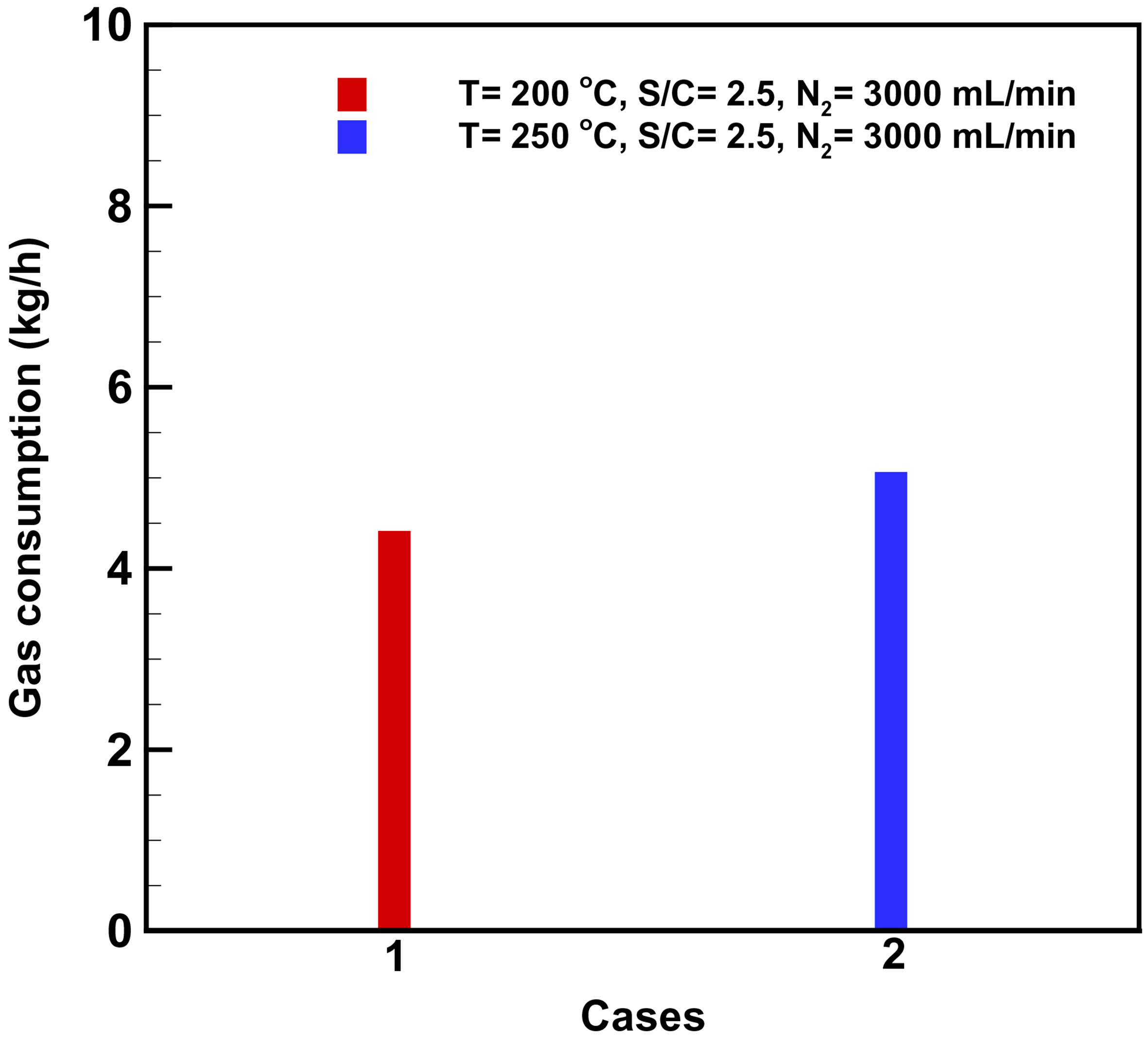
Figure 4. Hourly LPG consumption rates for Case 1 and Case 2 at different temperatures. LPG: Liquefied petroleum gas.
Figure 5 shows the temperature profiles in the boiler, preheating unit, and MSR unit. Temperature measurements are recorded once every 3 min during the experimental runs; Figure 5A shows the measurements from Case 1, and Figure 5B shows those from Case 2. In Case 1, the temperature inside the boiler ranges from 650 to 700 °C throughout the process, while the temperature in the preheating unit rises from approximately 400 °C at the outset to 450-
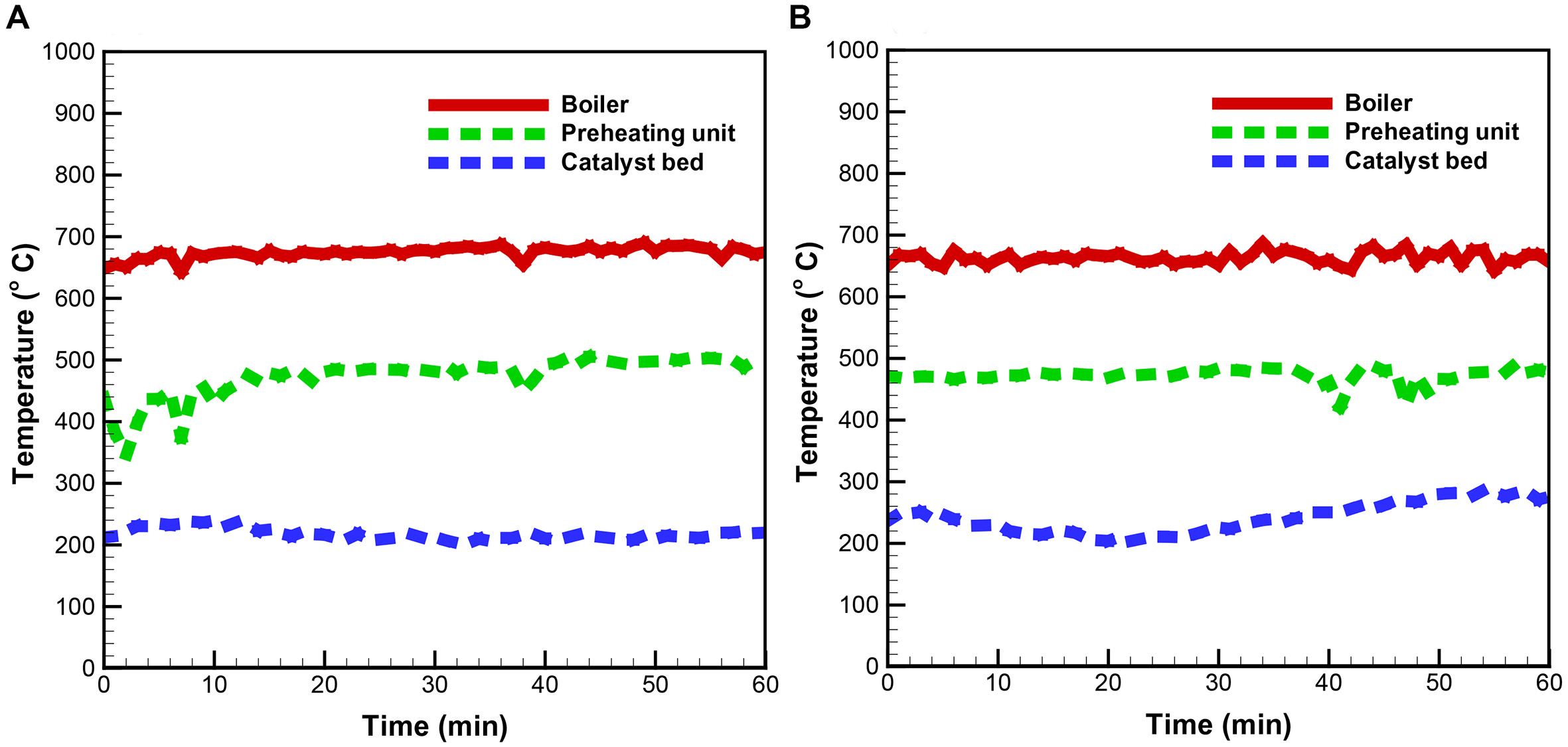
Figure 5. Temperature profiles for (A) Case 1 and (B) Case 2 at selected locations of the ITURS. ITURS: Integrated triple-unit recovery system.
Methanol steam reforming unit
Figure 6A shows the morphological features of the Cu-Zn bimetal catalyst used in this study, which is used for the MSR reaction. The catalyst consisted of cylindrical particles with dimensions of 5.0 mm in height and 5.12 mm in diameter. The catalyst bed has a porosity of 0.614. Figure 6B shows the scanning electron microscope (SEM) image of the catalyst, which exhibits a rugged, porous surface. The elemental composition of the catalyst examined via energy-dispersive X-ray spectroscopy (EDS) is shown in Figure 6C, and the results reveal that it is largely composed of CuO and ZnO, with oxygen accounting for over 60% of the mass, while Cu and Zn account for approximately 35% and 1.0%, respectively. In the MSR reaction, Cu and its oxides (Cu2O and CuO) serve as the primary active sites for methanol adsorption and dehydrogenation, leading to the formation of key intermediates, such as formate. ZnO functions as a structural and electronic promoter, stabilizing highly dispersed Cu species and tuning Cu surface properties. In addition, ZnO facilitates water activation and suppresses CO formation, thereby promoting the preferred CO2 pathway[30,31]. A comparison between the fresh and used catalyst compositions shows no significant change in the amounts of carbon and copper, indicating that coking is minimal after MSRs.
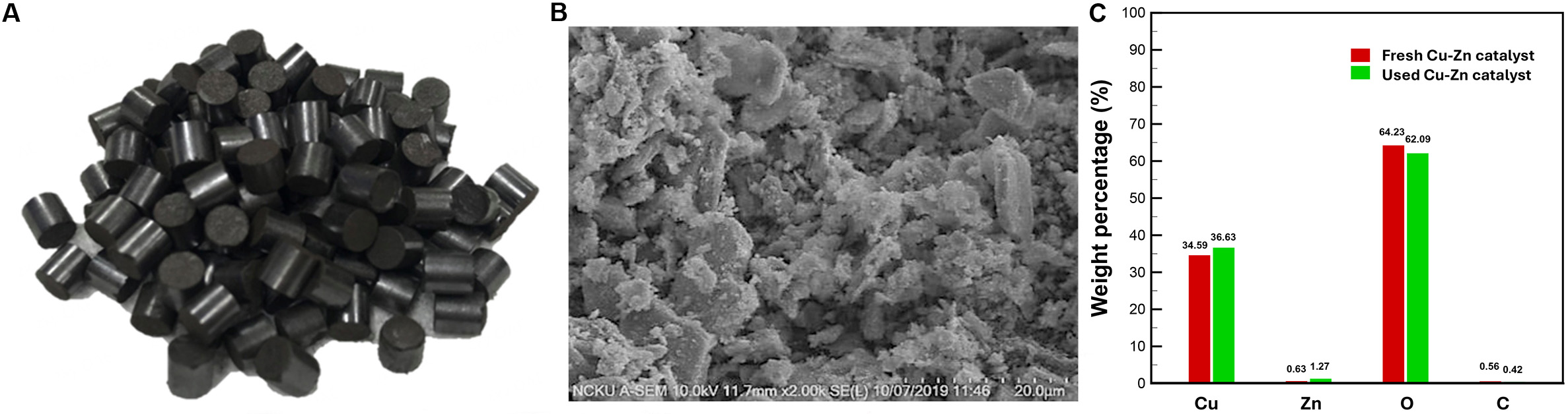
Figure 6. (A) Photograph of the pelletized Cu-Zn catalyst, (B) catalyst surface morphology observed by SEM at 2,000× magnification, and (C) corresponding elemental weight percentages obtained from EDS analysis. (Photograph taken by the authors). SEM: Scanning electron microscope; EDS: energy-dispersive X-ray spectroscopy.
Figure 7 shows the concentration time profiles of CO2, CO, CH4, and H2, the main gas species from MSR, under the operating conditions of Cases 1
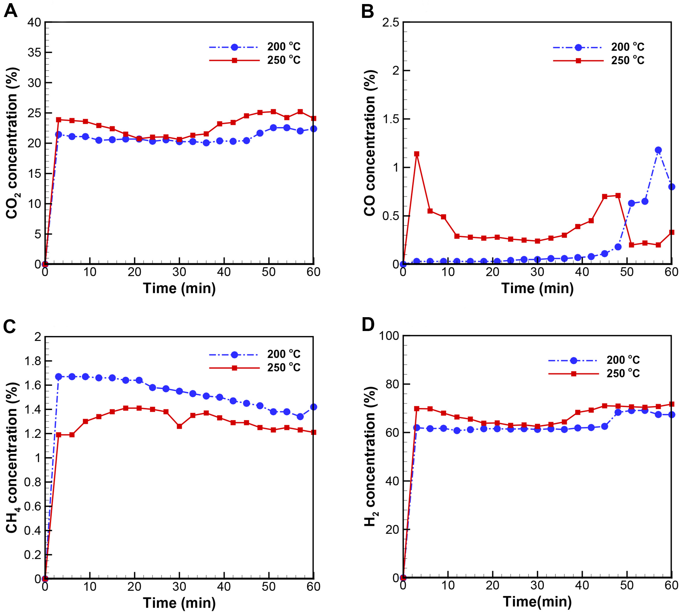
Figure 7. Concentration time profiles of the various MSR gaseous products: (A) CO2, (B) CO, (C) CH4, (D) H2 at reforming temperatures of 200 and 250 °C. MSR: Methanol steam reforming.
Compared to the CO concentration, the CH4 concentration [Figure 7C] showed minimal fluctuations between the two cases, ranging from 1.34% to 1.67% at 200 °C and from 1.19 to 1.38% at 250 °C. Lastly, the H2 concentration remains comparable in both cases, ranging from 61.19 to 69.13% at 200 °C and from 62.51 to 71.73% at 250 °C [Figure 7D]. Based on the measured gas concentrations, the H2 yield and CH3OH conversion can be calculated, as expressed below:
where
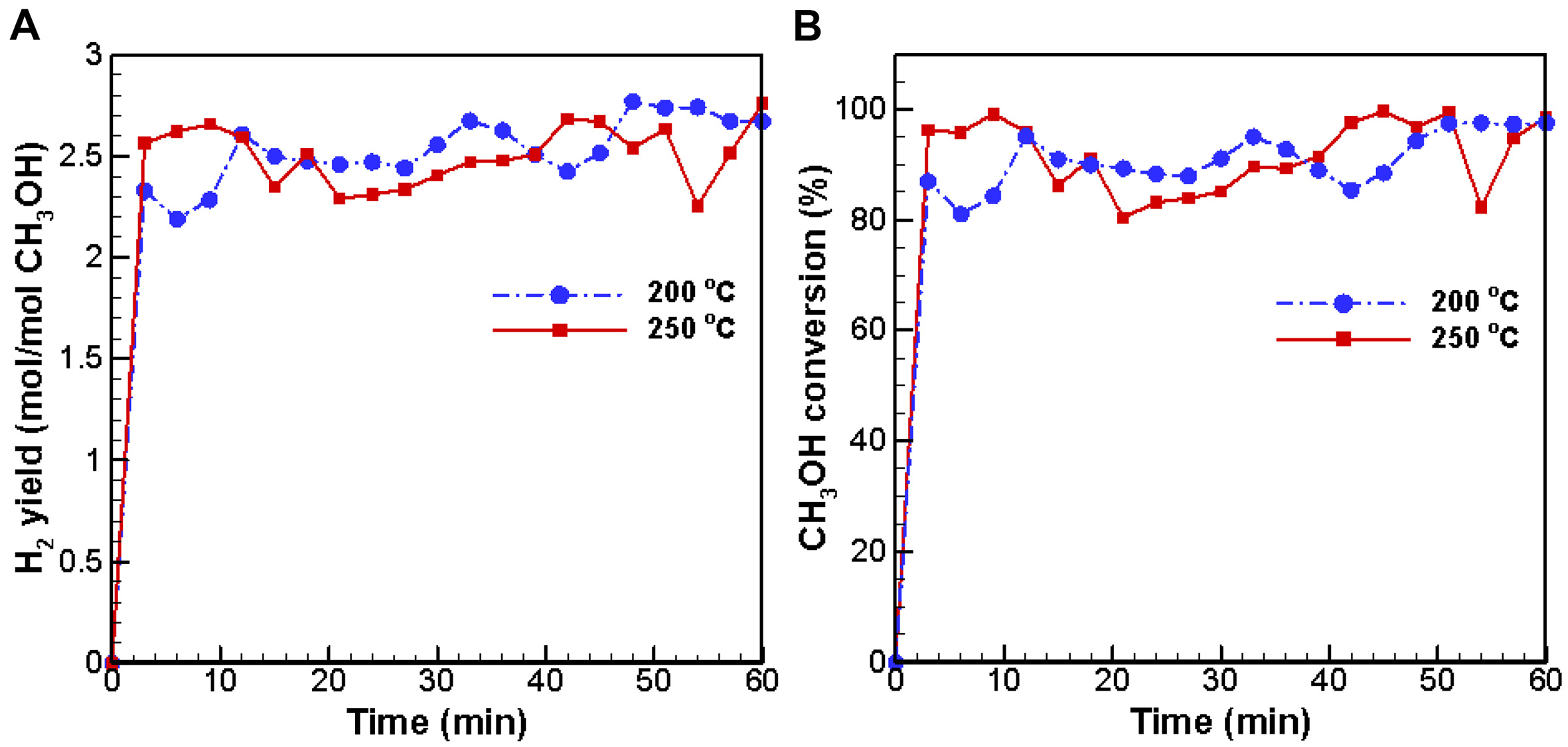
Figure 8. Conversion time profiles of (A) hydrogen yield and (B) methanol at 200 °C (Case 1) and 250 °C (Case 2).
TEG unit
As discussed in Section 2.4, two TEGs are attached outside the waste heat exhaust, creating a significant temperature difference to induce the flow of electrons from the “flue gas” side (i.e., hot side) to the “cooling water” side (i.e., cold side). On the “flue gas” side, the temperature at the inlet of the boiler-generated heat in Case 1 is around 300 °C, which then drops significantly to approximately 120 °C at the outlet, resulting in a significant temperature difference of over 180 °C [Figure 9A]. At the “cooling water” side, the inlet temperature for Case 1 remains steady at approximately 8-9 °C, while the outlet temperature reaches 16-17 °C, resulting to a temperature difference of about 8 °C [Figure 9B].
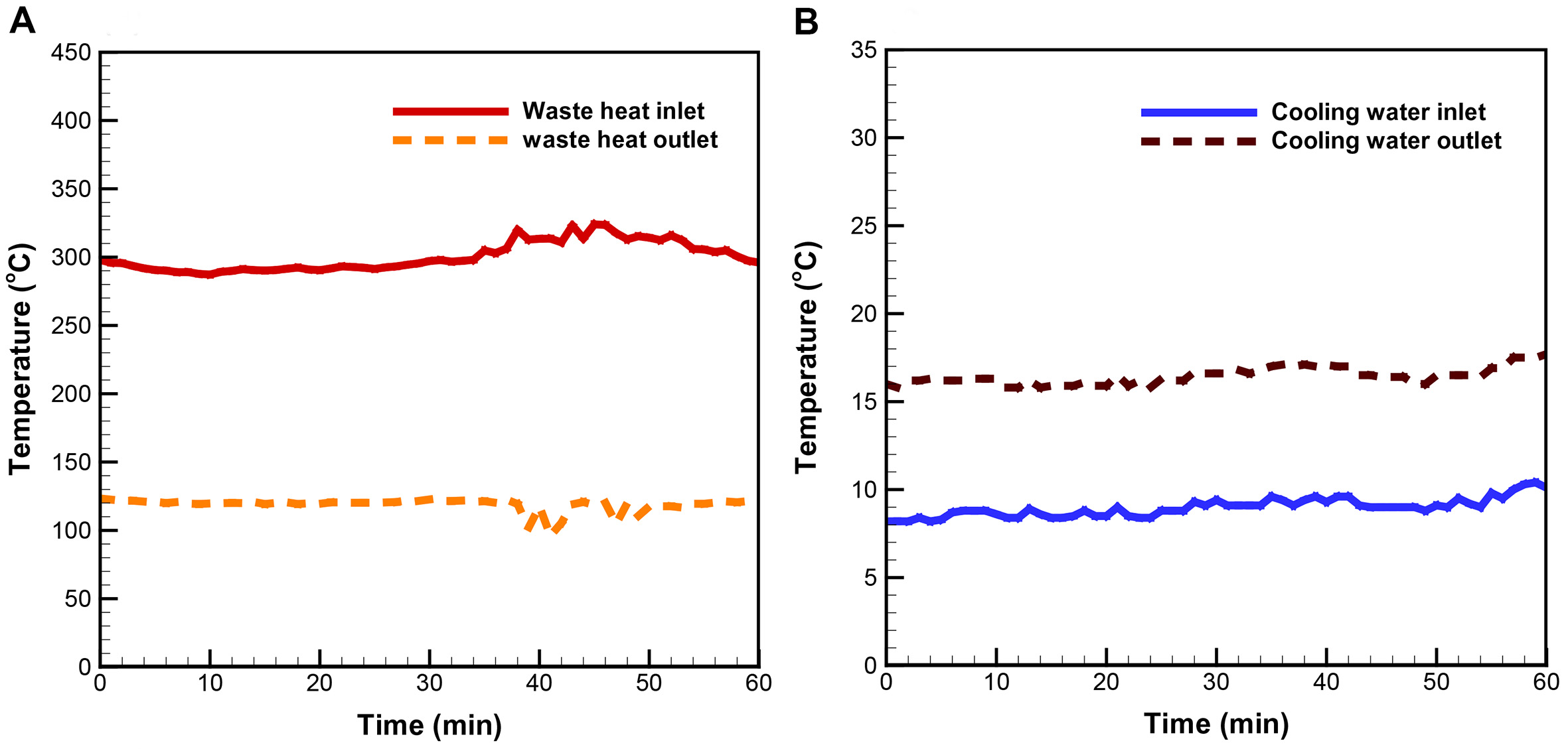
Figure 9. Temperature time profiles for Case 1: (A) flue gas at the inlet and outlet of the waste heat exhaust, and (B) cooling water at the inlet and outlet.
Temperature measurements in Case 2 demonstrate an identical pattern to those in Case 1 [Figure 10A and B]. For Case 2, the inlet temperature starts at 5 °C and rises to 8 °C after 60 min; meanwhile, the outlet temperature increases from 12 °C to approximately 18 °C, posing a temperature rise of about 7-10 °C throughout the process [Figure 10B]. While the flue gas at the inlet of the TEG unit remains as hot as 300 °C [Figure 9], the TEGs continue to work with high-efficiency due to the significant temperature difference (a high ΔT) created between the “flue gas” side and the “cooling water” side of the TEGs with continued supply of cold water flowing through the cooling tanks.
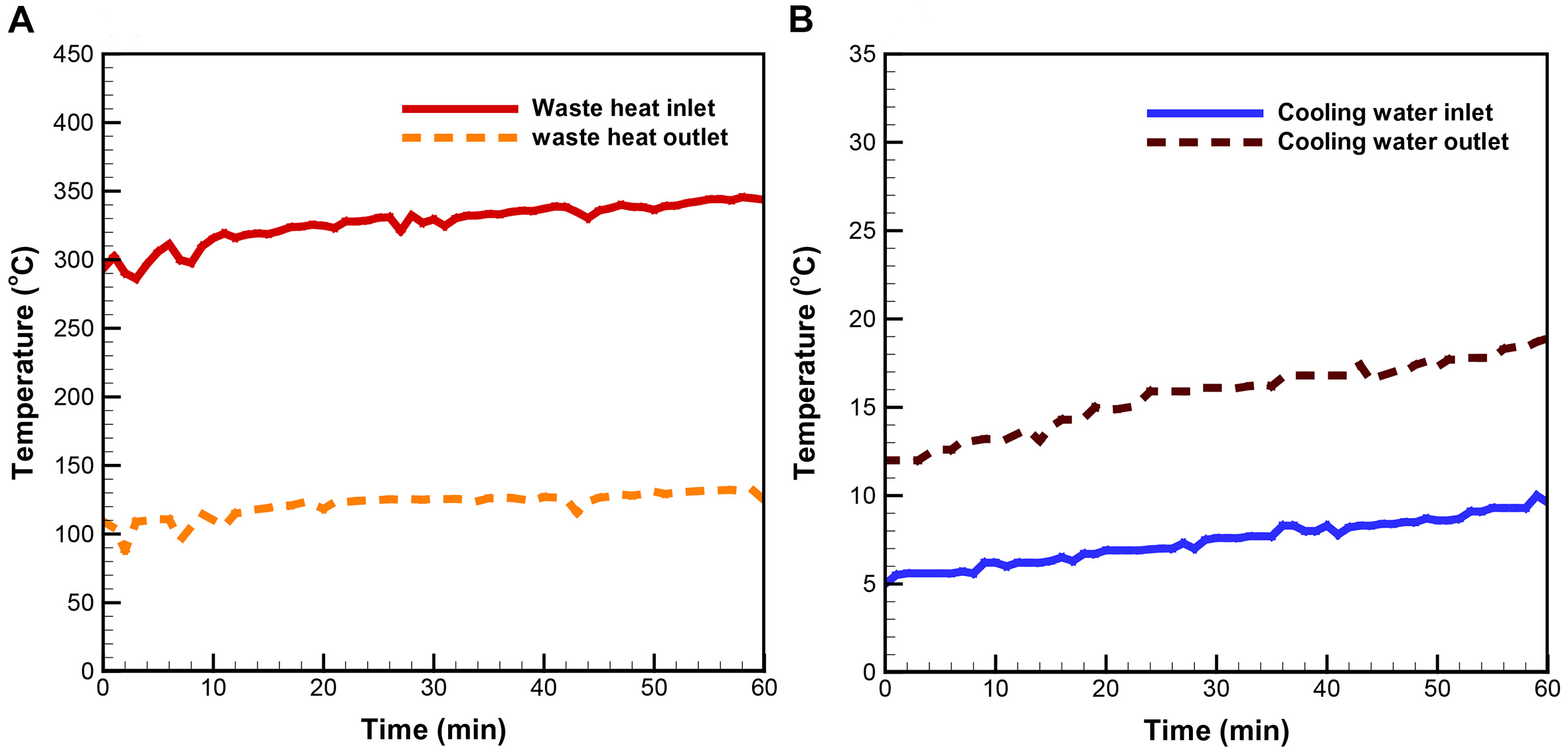
Figure 10. Temperature time profiles for Case 2: (A) flue gas at the inlet and outlet of the waste heat exhaust, and (B) cooling water at the inlet and outlet.
Figure 11 illustrates the time profiles of ΔT across the TEGs and their power outputs. Case 1, with an MSR operating temperature of 200 °C, generates 60.09 W (with a peak of 67.11 W) based on a ΔT of 291.38 °C. In Case 2, with an operating temperature of 250 °C, the ΔT is 319.19 °C, while the TEGs generate 63.37 W (with a maximum output of 73.82 W). These results show that the integrated system produces over 60 W across various operating conditions while effectively converting waste heat into electrical power via thermoelectric generation.
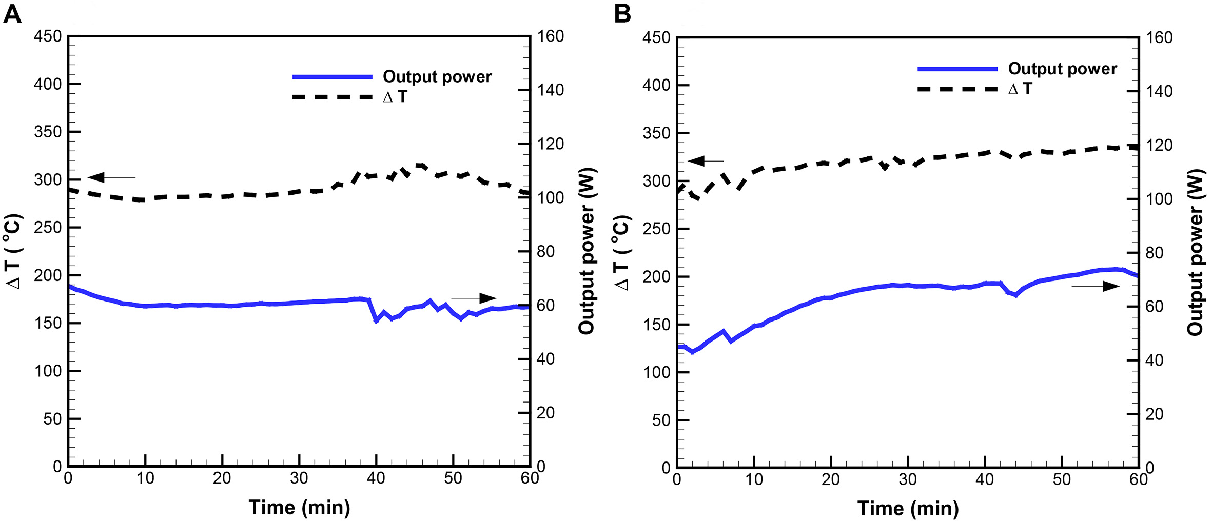
Figure 11. Time profiles of average temperature gradient (ΔT) and aggregate electrical power output for (A) Case 1 and (B) Case 2.
Energy conservation
The heat transfer across the preheating, MSR, and TEG units presented in Figure 12 is based strictly on the operating conditions of Case 1. This includes the initial enthalpy input derived from the specified LPG fuel and air flow rates for that particular run. First, heat is generated by burning LPG, which consists of 60 vol% propane and 40 vol% butane, with an HHV of approximately 2.38 × 10⁴ kcal·kg-1. LPG is injected into the boiler at a mass flow rate of approximately 0.074 kg·min-1. Air, containing 21% oxygen by volume, is supplied at a flow rate of 1.65 kg·min-1. In theory [Equation 7], under the condition of complete combustion, the total enthalpy released from the LPG is approximately 1,753.27 kcal·min-1. While the system is cooled with 20 kg·min-1 of cooling water, around 1,500.00 kcal·min-1 of enthalpy (H) is taken away. This is calculated from
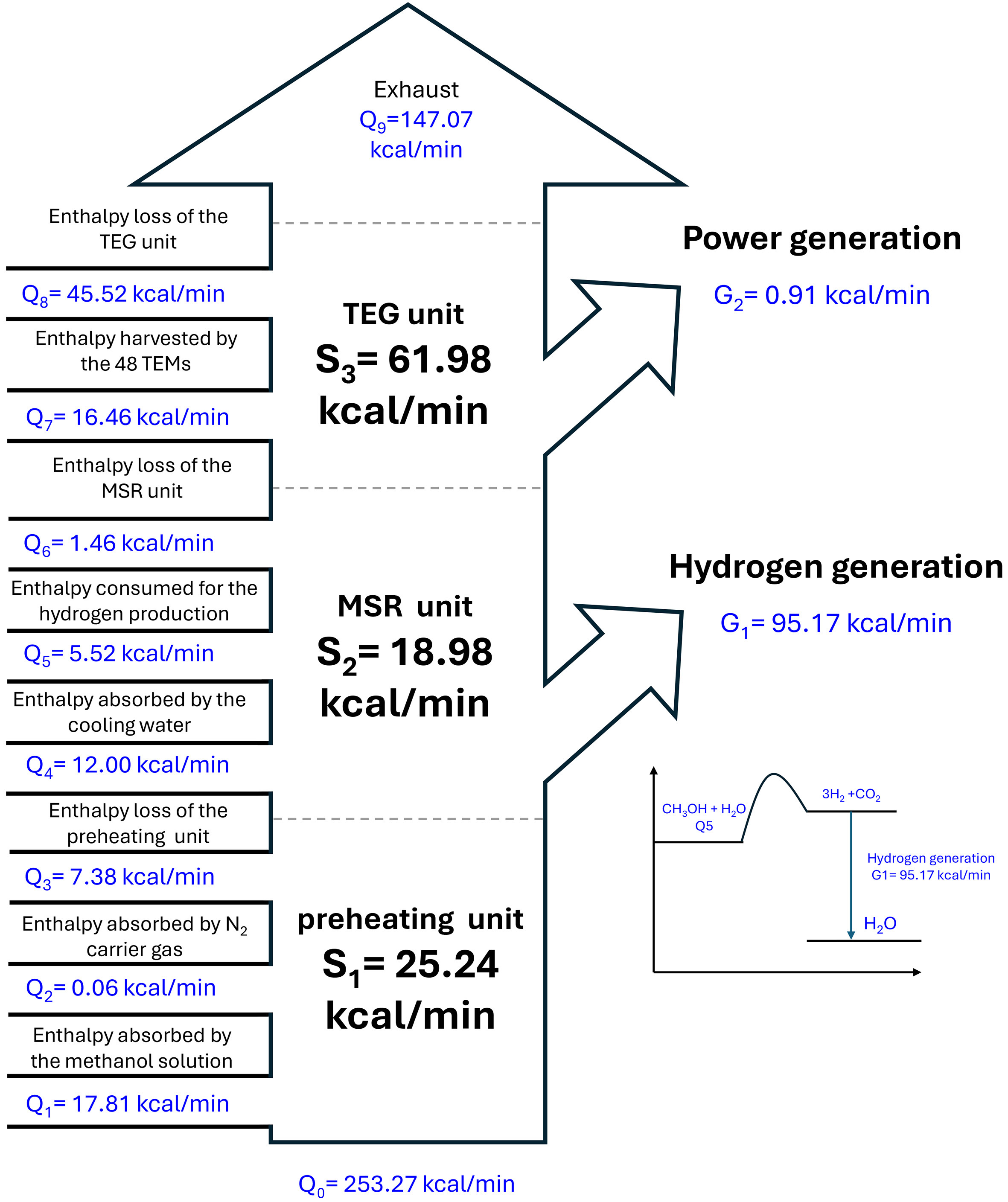
Figure 12. Enthalpy balance and distribution within the integrated triple-unit system. TEG: thermoelectric generation; MSR: methanol steam reforming.
In this energy balance analysis, the total heat generated by LPG combustion is 1,753.27 kcal·min-1. After accounting for the heat absorbed by the boiler cooling water (1,500.00 kcal·min-1), the remaining enthalpy is carried by the high-temperature flue gas into the ITURS. This flue gas serves as the primary energy source for the recovery units, with a total inlet enthalpy (Q0) estimated at 253.27 kcal·min-1 [Q0 = (1,753.27-1,500.00) kcal·min-1].
Preheating unit
As the first waste-heat recovery unit in the system, the preheating unit heats the methanol solution from 25 to 100 °C. This vaporizes the methanol and water, facilitating the subsequent MSR process. In the experiments, a methanol solution (CH3OH:H2O = 47.4:52.6 vol%) was pumped through a long copper tube (2 m) arranged in a helical coil configuration inside a hollow cylinder filled with hot flue gas at a flow rate of 40 mLmin-1. The enthalpy absorbed by the vaporized CH3OH and H2O in this process can be estimated from the energy required to vaporize them. Latent heat of 3.95 kcal·min-1 is required to vaporize CH3OH at 64.5 °C, while 11.35 kcal·min-1 is required to vaporize H2O at 100 °C. According to the enthalpy formula, the enthalpy absorbed by this process of vaporization is about 17.80 kcal·min-1 (Q1). To facilitate the flowing of the CH3OH/H2O vapors, N2, which has a Cp of 0.245 kcal·kg-1·°C-1, is pumped into the unit at a volume flow rate of
MSR unit
While waste heat from the hot flue gas activates the MSR unit, its temperature drops from approximately 390 to 327 °C on average, suggesting an enthalpy transfer from the flue gas into the unit of approximately 18.98 kcal·min-1 (S2). The MSR produces gases at a rate of 39.95 Lmin-1, with H2 accounting for 69.89 vol% and CO for 0.22 vol% of the total gaseous products. Based on this, the H2 yield is estimated at 2.81 g·min-1. Since H2 has an HHV of
According to the reaction formula of Equation 1, one mole of methanol produces 3 moles of hydrogen with an energy consumption of 11.88 kcal·mol-1. Based on this, an enthalpy consumption of 5.52 kcal·min-1 (Q5) can be attributed to the MSR process. To help remove H2O from the gaseous products, cooling water is circulated through a heat exchanger installed outside the MSR unit at a mass flow rate of 12 kg·min-1. Given a temperature increase from 15 to 16 °C, it is estimated that 12.00 kcal·min-1 of enthalpy is taken away by the cooling water (Q4). Taken together, enthalpy is estimated to be lost to the MSR unit at a rate of 1.46 kcal·min-1 (Q6 = S2 – Q4 – Q5).
TEG unit
Based on a 207 °C temperature difference between the hot flue gas inlet (327 °C) and outlet (120 °C) of the TEG unit, the enthalpy transfer from the flue gas to this final waste heat recovery unit is estimated at approximately 61.98 kcal·min-1 (S3). While some of this transferred energy contributes to power generation in the TEGs, the rest is removed from the system through convection. The efficiency of a TEG in generating electricity is estimated according to the following formula[35]:
According to Minnich et al.[36], Bi-Sb-Te-based thermoelectric modules exhibit a figure of merit (ZT) of approximately 0.69 under a temperature difference of 180 °C. With the average temperatures on the hot and cold sides of the unit being 230 and 50 °C, respectively, the TEG achieved a heat-to-electricity conversion efficiency of 1.47% under the operating conditions investigated in this study. Given a total power output of 0.91 kcal·min-1 (G2), enthalpy is found to be absorbed by the two TEGs at a rate of 16.46 kcal·min-1 (Q7). In light of conservation of energy, enthalpy is estimated to be lost to the unit at a rate of approximately 45.52 kcal·min-1 (Q8), which is derived from the subtraction of Q7 from S3.
In this study’s ITURS configuration, the measured electrical output is 0.91 kcal·min-1, equivalent to approximately 63.37 W, corresponding to a practical heat-to-electricity conversion efficiency of 1.47% [= G2 / (Q7 + Q8) × 100]. The lower experimental efficiency, compared with the theoretical estimation, is attributed to unavoidable heat loss to the surroundings, thermal resistance at material interfaces, and electrical resistance within the TEG assembly under industrial operating conditions.
Waste heat recovery and renewable energy
The flue gas entering the ITURS carries an enthalpy of 253.27 kcal·min-1 (Q0). Of this, 106.20 kcal·min-1 (S1 + S2 + S3) is transferred through the preheating, MSR, and TEG sections, corresponding to 41.93% of the available waste heat. The remaining 147.07 kcal·min-1 (Q9) leaves the system with the exhaust stream after passing through the recovery units. Within the recovery sequence, 9.96% (= S1 / Q0 × 100) of the inlet enthalpy is transferred to the preheating section, while 7.49% (= S2 / Q0 × 100) is supplied to sustain the endothermic MSR reaction. Another 24.47% is transferred to the TEG unit, supporting the temperature gradient required for power generation (= S3 / Q0 × 100). The arrangement of these units allows heat to be used progressively from higher to lower temperature regions rather than being discharged directly into the environment. Overall, the ITURS accounts for a total enthalpy utilization of approximately 41.93% from the flue gas across the recovery stages [= (Q0 – Q9) / Q0 × 100].
Under these operating conditions, the system produces a combined energy output of 96.08 kcal·min-1, including hydrogen with a higher heating value of 95.17 kcal·min-1 and electrical power equivalent to 0.91 kcal·min-1. It should be emphasized that the hydrogen energy mainly originates from the chemical energy stored in methanol, whereas the recovered flue-gas heat functions as the external energy source required to sustain methanol steam reforming and maintain continuous hydrogen production[37,38].
CONCLUSIONS
The proposed cascading ITURS configuration demonstrates the feasibility of utilizing industrial boiler waste heat for simultaneous hydrogen production and thermoelectric power generation. An energy balance analysis indicates that the flue-gas enthalpy is sequentially distributed across the preheating, methanol steam reforming, and thermoelectric generation units, in accordance with the temperature levels of each process. Approximately 18.98 kcal·min-1 of recovered heat is supplied to sustain the endothermic MSR reaction and maintain catalyst activity, while 61.98 kcal·min-1 is used to establish the temperature gradient required for thermoelectric power generation. The largest energy output from the system is associated with hydrogen production, reaching 95.17 kcal·min-1 based on the higher heating value of hydrogen. This energy primarily originates from the chemical energy stored in methanol and is partially from the recovered waste heat in the flue gas. In comparison, the electrical output from the TEG unit is
DECLARATIONS
Authors’ contributions
Investigation, data curation, writing - original draft, visualization: Chih, Y. K.
Writing - original draft, visualization, validation: Lee, K. T.
Formal analysis, writing - review and editing: Hsieh, J. C.
Resources, methodology, writing - review and editing: Lin, H. P.
Methodology, investigation, writing - review and editing: Uan, J. Y.
Conceptualization, methodology, investigation, funding acquisition, resource, supervision, writing - review and editing: Chen, W. H.
Availability of data and materials
The original contributions presented in this study are included in the article. Further inquiries can be directed to the corresponding author.
AI and AI-assisted tools statement
During the preparation of this manuscript, the AI tool ChatGPT (version 5.3, released 2026-04-09) was used solely for language editing. The tool did not influence the study design, data collection, analysis, interpretation, or the scientific content of the work. All authors take full responsibility for the accuracy, integrity, and final content of the manuscript.
Financial support and sponsorship
The authors gratefully acknowledge the financial support from the National Science and Technology Council, Taiwan, R.O.C., under the contracts MOST 110-2622-E-006-001-CC1, NSTC 112-2221-E- 006-111-MY3, NSTC 113-2221-E-006-195-MY3, and NSTC 112-2622-E-006-029- for this study. The authors gratefully acknowledge the use of EM000700 of NSTC 114-2740-M-006-001, belonging to the Core Facility Center of National Cheng Kung University. This research is also partly supported by the Higher Education Sprout Project, Ministry of Education, to the Headquarters of University Advancement at National Cheng Kung University (NCKU).
Conflicts of interest
Chen, W. H. serves as the Executive Editor of Advanced Energy Conversion, but was not involved in the editorial evaluation of this manuscript, including reviewer selection, manuscript handling, or publication decisions. The other authors have declared no conflicts of interest.
Ethical approval and consent to participate
Not applicable.
Consent for publication
Not applicable.
Copyright
© The Author(s) 2026.
REFERENCES
1. Chen, W. H. Progress in green energy and fuel for sustainability. Green. Energy. Fuel. Res. 2024, 1, 13-22.
2. Kaur, I.; Singh, P. State-of-the-art in heat exchanger additive manufacturing. Int. J. Heat. Mass. Transfer. 2021, 178, 121600.
3. Villa, G.; Corrales Ciganda, J. L.; Abrami, G.; Toppi, T. Absorption heat transformer and vapor compression heat pump as alternative options for waste heat upgrade in the industry. Energies 2025, 18, 3454.
4. Loni, R.; Najafi, G.; Bellos, E.; Rajaee, F.; Said, Z.; Mazlan, M. A review of industrial waste heat recovery system for power generation with Organic Rankine Cycle: recent challenges and future outlook. J. Clean. Prod. 2021, 287, 125070.
5. Zheng, S.; Chen, K.; Du, Y.; et al. Comparative analysis on off-design performance of a novel parallel dual-pressure Kalina cycle for low-grade heat utilization. Energy. Convers. Manage. 2021, 234, 113912.
6. Yang, F.; Yang, F.; Li, J.; Hu, S.; Yang, Z.; Duan, Y. Analysis of the thermodynamic performance limits of the organic Rankine cycle in low and medium temperature heat source applications. Sci. China. Technol. Sci. 2021, 64, 1624-40.
7. Jouhara, H.; Żabnieńska-góra, A.; Khordehgah, N.; et al. Thermoelectric generator (TEG) technologies and applications. Int. J. Thermofluids. 2021, 9, 100063.
8. Huo, D.; Tian, H.; Shu, G.; Wang, W. Progress and prospects for low-grade heat recovery electrochemical technologies. Sustain. Energy. Technol. Assess. 2022, 49, 101802.
9. Kim, K.; Kang, J.; Lee, H. Hybrid thermoelectrochemical and concentration cells for harvesting low-grade waste heat. Chem. Eng. J. 2021, 426, 131797.
10. Yu, C.; Park, J.; Ryoun Youn, J.; Seok Song, Y. Integration of form-stable phase change material into pyroelectric energy harvesting system. Appl. Energy. 2022, 307, 118212.
11. Arias, D. M.; García-valladares, O.; Besagni, G.; Markides, C. N. A vision of renewable thermal technologies for drying, biofuels production and industrial waste, gas or water recovery. Appl. Therm. Eng. 2023, 223, 120022.
12. Johnson, I. Choate, W.T.; Davidson, A. Waste heat recovery. Technology and opportunities in U.S. industry. 2008: United States.
13. Boretti, A.; Banik, B. K. Advances in hydrogen production from natural gas reforming. Adv. Energy. and. Sustain. Res. 2021, 2, 2100097.
14. Gholami, T.; Pirsaheb, M. Review on effective parameters in electrochemical hydrogen storage. Int. J. Hydrogen. Energy. 2021, 46, 783-95.
15. Rabell, G. O.; Cruz, M. A.; Juárez-ramírez, I. Hydrogen production of ZnO and ZnO/Ag films by photocatalysis and photoelectrocatalysis. Mater. Sci. Semicond. Process. 2021, 134, 105985.
16. Lepage, T.; Kammoun, M.; Schmetz, Q.; Richel, A. Biomass-to-hydrogen: a review of main routes production, processes evaluation and techno-economical assessment. Biomass. Bioenergy. 2021, 144, 105920.
17. Baraj, E.; Ciahotný, K.; Hlinčík, T. The water gas shift reaction: catalysts and reaction mechanism. Fuel 2021, 288, 119817.
18. Li, H.; Ma, C.; Zou, X.; Li, A.; Huang, Z.; Zhu, L. On-board methanol catalytic reforming for hydrogen production - a review. Int. J. Hydrogen. Energy. 2021, 46, 22303-27.
19. Bai, S.; Liu, C. Overview of energy harvesting and emission reduction technologies in hybrid electric vehicles. Renew. Sust. Energy. Rev. 2021, 147, 111188.
20. Chen, W.; Lee, K.; Chih, Y.; et al. Novel renewable double-energy system for activated biochar production and thermoelectric generation from waste heat. Energy. Fuels. 2020, 34, 3383-93.
21. Ge, Y.; He, K.; Xiao, L.; Yuan, W.; Huang, S. Geometric optimization for the thermoelectric generator with variable cross-section legs by coupling finite element method and optimization algorithm. Renew. Energy. 2022, 183, 294-303.
22. Yang, L.; Chen, Z. G.; Dargusch, M. S.; Zou, J. High performance thermoelectric materials: progress and their applications. Adv. Energy. Mater. 2017, 8, 1701797.
23. He, W.; Zhang, G.; Zhang, X.; Ji, J.; Li, G.; Zhao, X. Recent development and application of thermoelectric generator and cooler. Appl. Energy. 2015, 143, 1-25.
24. Park, J. G.; Lee, Y. H. High thermoelectric performance of Bi-Te alloy: defect engineering strategy. Curr. Appl. Phys. 2016, 16, 1202-15.
25. Kosuda, O.; Hikichi, T.; Kido, O.; Nishiyama, N. Development of air-cooled compact Organic Rankine Cycle power generation technology utilizing waste heat. Energy. Procedia. 2017, 129, 559-66.
26. Usman, M.; Yamada, T. Methanol reforming for hydrogen production: advances in catalysts, nanomaterials, reactor design, and fuel cell integration. ACS. Eng. Au. 2025, 5, 314-46.
27. Shen, Z.; Liu, X.; Chen, S.; Wu, S.; Xiao, L.; Chen, Z. Theoretical analysis on a segmented annular thermoelectric generator. Energy 2018, 157, 297-313.
28. Gao, Z.; Wei, Y.; Cheng, Z.; He, Y.; Gao, Q. Study on solar-driven methanol steam reforming process in parabolic trough solar receiver-reactors by developing an optical-thermal-chemical model of realistic porosity distributions. Appl. Energy. 2023, 347, 121418.
29. Zhao, N.; Wang, J.; Yao, Z.; Shao, Y.; Tian, Y.; Liu, W. A novel multi-objective optimization model of solar-driven methanol steam reforming system combining response surface methodology and three-dimensional numerical simulation. Energy. Convers. Manag. 2024, 300, 117986.
30. Liu, D.; Zhang, M.; Zhao, L.; Guo, X.; Xu, G.; He, H. Mechanistic insights into methanol steam reforming on copper catalysts: dynamics of active sites and reaction pathway. J. Catal. 2025, 442, 115922.
31. Yan, H.; Li, D.; Jiang, Z.; et al. Promotion of Cu/ZnO/Al2O3 by Fe towards methanol steam reforming reaction. Appl. Catal. B. Environ. Energy. 2025, 365, 124984.
32. Kim, J. H.; Jang, Y. S.; Kim, J. C.; Kim, D. H. Anodic aluminum oxide supported Cu-Zn catalyst for oxidative steam reforming of methanol. Korean. J. Chem. Eng. 2019, 36, 368-76.
33. Sun, Z.; Fang, S.; Lin, Y.; Hu, Y. H. Photo-assisted methanol steam reforming on solid solution of Cu-Zn-Ti oxide. Chem. Eng. J. 2019, 375, 121909.
34. Ritzkopf, I.; Vukojević, S.; Weidenthaler, C.; Grunwaldt, J.; Schüth, F. Decreased CO production in methanol steam reforming over Cu/ZrO2 catalysts prepared by the microemulsion technique. Appl. Catal. A. Gen. 2006, 302, 215-23.
35. Snyder, G. J.; Snyder, A. H. Figure of merit ZT of a thermoelectric device defined from materials properties. Energy. Environ. Sci. 2017, 10, 2280-3.
36. Minnich, A. J.; Dresselhaus, M. S.; Ren, Z. F.; Chen, G. Bulk nanostructured thermoelectric materials: current research and future prospects. Energy. Environ. Sci. 2009, 2, 466.
37. Abbas, H. F.; Wan Daud, W. Hydrogen production by methane decomposition: a review. Int. J. Hydrogen. Energy. 2010, 35, 1160-90.
Cite This Article
How to Cite
Download Citation
Export Citation File:
Type of Import
Tips on Downloading Citation
Citation Manager File Format
Type of Import
Direct Import: When the Direct Import option is selected (the default state), a dialogue box will give you the option to Save or Open the downloaded citation data. Choosing Open will either launch your citation manager or give you a choice of applications with which to use the metadata. The Save option saves the file locally for later use.
Indirect Import: When the Indirect Import option is selected, the metadata is displayed and may be copied and pasted as needed.
About This Article
Copyright

Data & Comments
Data
0


Comments
Comments must be written in English. Spam, offensive content, impersonation, and private information will not be permitted. If any comment is reported and identified as inappropriate content by OAE staff, the comment will be removed without notice. If you have any queries or need any help, please contact us at [email protected].